A Welcome Sight: The Y-Structure
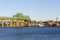
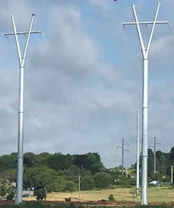
In early 1920s Massachusetts, the Somerset-Fall River lines were installed on Industrial Era lattice structures. According to “Somerset,” a pictorial history book of the town by James Edward Bradbury, the lines were designed to connect the second unit at Montaup Electric Co.’s Somerset generation plant, in the town of Somerset, across the Taunton River, to Hathaway substation in the city of Fall River. Now, a century later, the lattice towers — dubbed the Godzilla structure — have been replaced by four 225-ft (69-m) tall “cheerleaders on the city waterfront” and are “happily futuristic,” as described by local media.
The result of a partnership between National Grid and consulting design firms Commonwealth Associates Inc. and CDM Smith Inc., the sleek, modern Y-structures are part of a larger asset condition replacement (ACR) project. City officials credit this innovative design with freeing up valuable waterfront property for community and economic development. Work began in fall 2017 and was completed in winter 2018, and the 115-kV Z1/Y2 transmission lines are now in service.
A Brief History
The power generation industry dominated Somerset after World War I. Related job creation enhanced the quality of life. At the same time, nearby Fall River enjoyed a booming mill industry. By 1923, Fall River Electric Lighting Co.’s (FRELCO’s) Hathaway Street generation plant reached capacity while serving the mills. Montaup’s second unit and associated transmission lines were needed to help serve the load, reported William A. Moniz in an article, Thomas Edison’s Visits to Fall River Key in Establishing One of Nation’s Earliest Electric Companies, published Jan. 8, 2015, on Southcoasttoday.com.
The Somerset plant’s location required the lines to cross the river with a clearance that would permit the safe travel of barges. According to Fundinguniverse.com, the design was performed by Stone and Webster, using 19 No. 9 Copperweld conductor carried on A9 steel lattice towers. Over the decades, the two 1208-ft (368-m) spans and 207-ft (63-m) tall towers served their purpose, but not without continuing issues, including an aviation near miss, according to the National Transportation Safety Board.
Functionality + Aesthetics
National Grid was aware of the impact a very large, visible transmission tower would have on the Somerset and Fall River skylines. The utility’s director at the time, Mark Browne, set the vision: a robust, contemporary and elegant design; one that delivers reliable power to the communities, leverages technological advances made over the last century, and enhances the waterfront and skylines. National Grid tasked Commonwealth and CDM Smith to implement this vision.
Several serious engineering challenges had to be tackled:
- A history of shield wire ice buildup and ice falling onto the conductors
- Unfavorable subsurface conditions, especially on the wharf side of the river
- A high-water table
- Close proximity to homes and businesses
- Massachusetts Department of Public Utilities license requirements.
The conceptual design phase began with structural behavior and aesthetics screening of three structure types: H-frames, monopoles and lattice. The H-frame and lattice tower options would use a horizontal conductor configuration, while the monopole’s configuration would be vertical.
Large footprints of both the H-frame and lattice structures combined with the limited wharf area availability on the river’s east side eliminated those alternatives from consideration. The monopole option also generated concerns. The required vertical clearance over the river and conductor galloping would necessitate a structure more than 270 ft tall. In addition, this height would not alleviate the shield wire icing concern and associated energized shield wire issue.
The Y-Structure
National Grid and Commonwealth team members needed to come up with a unique monopole design that would accomplish the following:
- Reduce the structure footprint
- Be configured horizontally
- Eliminate the shield wire icing issue.
The unique design incorporating each of these elements was a Y-structure. Given the crossing’s proximity to popular local dining and recreational attractions, like Bicentennial Park, selecting a monopole with an aesthetically pleasing appearance was critical. The diagonal members that transfer the load from the conductors and shield wires to a single point on the pole sweep gracefully using a uniform taper. The compact lines and elegant curves provide an added benefit: the creation of a dynamic new signature for both Somerset and Fall River.
Once the structure type was selected, multiple considerations were analyzed to develop its geometry. The distance between the conductors and shield wire was determined based on galloping elimination and electrical clearance requirements under multiple weather cases. Diagonal structural members were configured such that the electrical clearance between the steel members and the center phase jumper location was met.
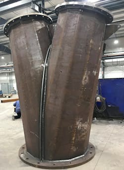
The necessary design specifications posed fabrication challenges. For efficiency and aesthetics, it was critical to ensure a uniform taper along the entire length of the structure. To avoid two significantly dissimilar structural sections at the flange connection, Commonwealth specified a three-way bolted flange junction connection. This specification allowed for a singular transition section, ensuring the taper of the pole looked uniform from both the transverse and longitudinal directions. The Y-junction was fabricated as two separate pieces split on the transverse bisector of the pole and welded together on a bisector plate to ensure a sufficient structural connection.
Manufacturing and delivery processes resulted in design and specification constraints. Transportation limitations capped the structure section lengths at 50 ft (15 m). Each section had to be shipped from the manufacturing facility in Ohio to a galvanization facility in Kansas — at the time, assumed to be the largest kettle in the U.S. — and then, ultimately, to the project location in Massachusetts. The structure was so large a full-scale load test to verify structural capacity was not available in the U.S. Accordingly, only a constructability fit-up was performed prior to galvanizing. It was witnessed by both National Grid and Commonwealth to avoid issues during the site structure erection.
Commonwealth considered innovation throughout the design process and was actively looking for ways to reduce structure heights and project costs. For example, high-temperature, low-sag aluminum conductor composite-reinforced (ACCR) conductor was evaluated and selected over National Grid’s standard aluminum conductor steel-reinforced (ACSR) conductor. ACCR conductor has a high-strength, lightweight aluminum core, with the outer strands comprised of hardened aluminum-zirconium alloy that are helically stranded for greater strength and conductivity. ACCR conductor is similar to ACSR dimensionally and in construction, but it has a higher strength-to-weight ratio and lower thermal expansion. This allows for a lower sag at higher operating temperatures. The selection of this conductor resulted in a structure height reduction of over 20 ft (6 m) per structure.
The Foundation
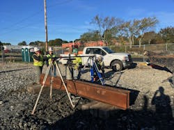
To accommodate the Y-structure’s height and slender monopole configuration, the foundation would be subject to unusually large overturning forces. A conventional drilled pier foundation would be impractical to support the Y-structure monopole; initial estimates indicated the need for an 18-ft (5.5-m) diameter drilled pier foundation extending 45 ft (14 m) belowground. The drilled piers would require complex construction techniques, including a steel casing, and the use of slurry to maintain sidewall stability and prevent bottom heave under high groundwater conditions. The heavy-duty crane-mounted rigs and ancillary equipment required for installation of such large-diameter drilled piers with steel casing also would require a large work area and specially prepared work platforms.
Further, on-site geotechnical exploration revealed debris consisting of bricks, glass and wood within the fill material, which could significantly impede the advancement of large-diameter drilled piers. The National Grid director at the time, Lisa Sasur, challenged the design team to develop a more cost-effective foundation alternative, one that provided adequate support against the unusually large overturning moments and could be constructed with standard foundation construction techniques and equipment while maintaining a minimal surface footprint.
Rising to the design challenge, the team’s first step was to evaluate the differing ground conditions, with bedrock near the ground surface on the Somerset side and loose soil conditions at depth on the Fall River side. After evaluating several different foundation types, CDM Smith developed two separate foundation systems, each appropriate to the ground conditions present: on the Somerset side, a concrete foundation bearing on bedrock with 28 drilled-in rock anchors, and on the Fall River side, a concrete pile cap with 25 driven steel H-piles.
The concrete portions of the foundations would be cast in place and only need to be about 10 ft (3 m) deep, eliminating the challenges associated with advancing large-diameter drilled piers through fill material containing debris and potential obstructions. The rock anchors and H-piles could be installed using standard pile driving equipment and rigs, which could be accommodated within the limited working area available on the project site.
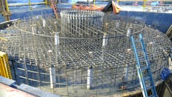
To provide stability for the base of the Y-structures, the pile caps had to be 30 ft (9 m) in diameter. However, having this large of a foundation visible at the ground surface was not desirable. Therefore, foundation designers reduced the pile cap diameter down to only 18 ft at the ground surface. Designers developed special detailing of the top mat of rebar, and the narrower top portion of the pile cap had to be placed separately from the lower sections of the foundation. The resulting foundation appeared slimmer and more proportional to the size of the monopole base. Closely spaced top rebar passing through the center of the pile caps had to be carefully threaded through tightly grouped large-diameter anchor bolts for the monopole. Rebar also had to be worked around rock anchor sleeves and steel H-piles.
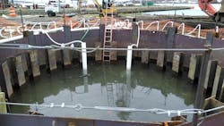
Dewatering operations, required for foundation excavation and concrete placement, were a major challenge given the proximity of the structures to the Taunton River and the associated high groundwater levels. On the Somerset side, localized submersible sump pumps were successfully employed to remove groundwater from the excavation pits. However, at Fall River, a robust well-point system was needed around the perimeter of the foundations to keep groundwater below the bottom of the excavation pits.
As excavation progressed for the Y-structure foundations, higher-than-anticipated groundwater inflow rates were encountered, which required the use of alternate dewatering techniques. In addition, the design team worked closely with environmental scientists and authorities who instructed all groundwater either be transported and disposed of off-site or allowed to infiltrate back into the site soils within 100 ft (30.5 m) of the work area. The team exceeded the expectations of authorities by providing two large 20,000-gal (75,708-L) frac tanks for temporary storage of groundwater before transporting it off-site for disposal.
Placing concrete for the foundation in cold weather was another complicating factor. From early October to late January, the cold temperatures required concrete placement operations be tented and heated. Concrete is susceptible to damage if allowed to freeze during the first few days of placement when it has not attained more than 500 psi strength; therefore, the concrete temperatures were monitored daily following each placement.
Behind the scenes, the engineering team planned construction operations to safely support the very large tower reaction forces. It was critical to confirm the deep foundation elements (rock anchors and steel H-piles) could provide the specified design capacities. Performance testing was conducted on a sacrificial rock anchor, which confirmed the design recommendation that only 10 ft of embedment into competent rock was necessary to achieve the required tension loads. Performance tests on the sacrificial rock anchor were repeated multiple times to ensure water tightness requirements were met in accordance with the specifications. For the H-piles, high-strain dynamic pile driving analyzer (PDA) testing of two indicator piles, and up to two times the design load, confirmed the piles had satisfactory capacity at the depths to which they were installed.
Vision Achieved
With the Y-structures complete, it was time to remove the four existing lattice towers. The towers were dismantled in sections from top to bottom. The project was overwhelmingly embraced by the public because of its signature look. The overall quality of life in the immediate area has improved through the development of Bicentennial Park, and better views have been achieved for the tenants in Commonwealth Landing.
National Grid’s rebuild vision has been satisfied, with a signature crossing to accent the city, provide reliable power and make maintenance easier — all while honoring the past.
Scott M. Hartley ([email protected]), P.E., is a senior lead transmission engineer and project manager with Commonwealth Associates Inc. He has 17 years of experience in both transmission line and distribution design and has been with Commonwealth since 2014. Hartley is a Professional Engineer who has been involved in many innovative projects and continues to grow his engineering knowledge.
Debra M. Justice, P.E., was formerly a senior electrical engineer and project manager in the transmission lines department for Commonwealth Associates Inc. She has over 30 years of experience in the electric utility industry designing T&D lines.
Timothy M. Montgomery ([email protected]), P.E., has 18 years of experience as a structural engineer, specializing in design of industrial structures and investigation and rehabilitation of concrete structures. Montgomery has designed numerous structures, including transmission tower foundations, liquid-containing structures and various types of industrial buildings. He also has performed numerous investigations of various types of structures. He is a member of the American Institute of Steel Construction; the American Concrete Institute, currently serving on Committee 562; and the International Concrete Repair Institute, currently serving on the Board of Directors for the New England chapter. He also has written and presented on concrete repair and durability.
Amit Urs ([email protected]), P.E., is a lead engineer in the electric transmission line engineering group. He joined National Grid in 2007. His deep
understanding and specific experience in structural engineering are crucial to his role as a lead engineer on a wide range of projects. Urs is a Professional
Engineer and has a passion for engineering, focusing on innovative ways to reduce project costs and improving safety.
Nicole Maglione ([email protected]), P. E., is the director of engineering, electric plan and design in the transmission line department – New England Region for National Grid.
About the Author
Scott M. Hartley
Scott M. Hartley ([email protected]), P.E., is a senior lead transmission engineer and project manager with Commonwealth Associates Inc. He has 17 years of experience in both transmission line and distribution design and has been with Commonwealth since 2014. Hartley is a Professional Engineer who has been involved in many innovative projects and continues to grow his engineering knowledge.
Debra M. Justice
Debra M. Justice ([email protected]), P.E., is a senior electrical engineer and project manager in the transmission lines department with Commonwealth Associates Inc. She has over 30 years of experience in the electric utility industry designing T&D lines.
Timothy M. Montgomery
Timothy M. Montgomery ([email protected]), P.E., has 18 years of experience as a structural engineer, specializing in design of industrial structures and investigation and rehabilitation of concrete structures. Montgomery has designed numerous structures, including transmission tower foundations, liquid-containing structures and various types of industrial buildings. He also has performed numerous investigations of various types of structures. He is a member of the American Institute of Steel Construction; the American Concrete Institute, currently serving on Committee 562; and the International Concrete Repair Institute, currently serving on the Board of Directors for the New England chapter. He also has written and presented on concrete repair and durability.
Amit Urs
Amit Urs ([email protected]), P.E., is a lead engineer in the electric transmission line engineering group. He joined National Grid in 2007. His deep understanding and specific experience in structural engineering are crucial to his role as a lead engineer on a wide range of projects. Urs is a Professional Engineer and has a passion for engineering, focusing on innovative ways to reduce project costs and improving safety.
Nicole Maglione
Nicole Maglione ([email protected]), P. E., is the director of engineering, electric plan and design in the transmission line department – New England Region for National Grid.
