What can a utility do when an existing transmission line does not meet clearance criteria? One option would be to build a new transmission line, but this would be expensive and could take many years just to get the required permits. Instead, ITC Holdings Corp. — faced with such an issue — opted to raise 25 steel lattice towers by 10 ft or 20 ft (3 m or 6 m) each to enable the line to operate at its design rating, saving both time and money. The methodology and cost considerations involved in raising existing lattice towers make an interesting story that includes the project’s critical path items and potential improvements.
As the largest independent electric transmission utility in the U.S., ITC invests in the electric transmission grid to improve reliability and expand access to energy markets. This enables new generating resources to interconnect to its transmission systems and lowers the overall cost of delivered energy. ITC owns and operates high-voltage transmission facilities in Michigan, Iowa, Minnesota, Illinois, Missouri, Kansas and Oklahoma. ITC’s operations in Michigan include most of the Lower Peninsula, largely served by its Michigan Electric Transmission Co. (METC) operating subsidiary.
Prior to ITC’s acquisition of METC in 2006, clearance issues had forced a derating of the 345-kV Argenta-Palisades transmission line as a result of excessive line sag. In 2009, ITC’s transmission engineers investigated the option of restoring this critical 40-mile (64-km) double-circuit line to its design rating to meet increasing demand. The utility confirmed the need for the uprating and identified three alternative approaches to accomplish its goal without having to build a new transmission line. After conducting a thorough evaluation, the utility was able to make an informed decision on the best approach.
Alternative Approaches
The first approach ITC reviewed was replacing 25 existing steel lattice towers with new steel lattice towers. The second approach was replacing the existing lattice towers with new steel monopoles. The third approach was raising the existing steel lattice towers with new tower extensions.
After studying the projected length of service disruption, effects on reliability of each approach, and the direct and indirect costs — including engineering, procurement and construction costs — ITC decided to raise the existing steel lattice towers onto new extensions. The utility contracted with Black & Veatch to perform the detailed design work.
Decision Process
Black & Veatch began the project with a detailed review of the 345-kV Argenta-Palisades transmission line, including the sag clearance issues that led to its derating. ITC considered the multiple criteria to determine the best approach for uprating the line. Given the voltage of the line and its criticality in the ITC system, providing a solution that would minimize overall construction outage time while enabling the line to be put back into service quickly during the construction process would enhance reliability; therefore, this was a high priority. Solutions allowing portions of the construction to be performed safely while the line was energized also were evaluated.
The work needed to be conducted on an aggressive schedule, and ITC evaluated numerous aspects to ensure the overall project would be completed on time. These aspects included engineering time for detailed design, lead times for materials and construction time. Additionally, and to assess the complete economic impact of the project accurately, an analysis of the direct project costs such as engineering, procurement and construction was required along with the indirect costs — most critically, outage length.
Using the established criteria, ITC developed several approaches for consideration. Modified conductor attachments and insulator assemblies to raise conductor attachment points were ruled out when it was determined they would not provide enough additional clearance to resolve the issue with the 345-kV line. As a result, alternatives involving structure replacement and modification were developed.
Replacing existing steel lattice towers with new steel lattice towers and adding new mid-span steel lattice towers was evaluated. This alternative would have included installing as many as 25 complete new steel lattice towers 10 ft to 20 ft taller than the existing structures, installing new foundations, and removing and disposing of the existing steel lattice towers. In cases where the installation of mid-span structures was an option, this decision would eliminate the need to remove existing structures. A slight variation to this alternative would be to use steel monopoles instead of lattice structures.
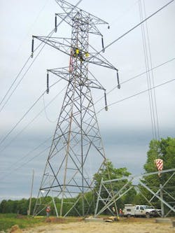
A review of the 25 existing lattice towers revealed none of them used the maximum tower height for its type. Therefore, all the towers could be raised the required 10 ft to 20 ft, using the original tower components. This alternative would include designing new leg extensions, installing new foundations near each existing structure, building the new leg extensions on the new foundations, unclipping all wires from their suspension clamps, placing all wires in stringing blocks, unbolting the existing towers from the stub angles of their existing grillage foundations, lifting and moving each tower to its new location, and bolting each tower to the new leg extensions.
ITC’s evaluation revealed the alternative involving the use of tower extensions had the least negative impact from a reliability perspective. It would require an outage only for the unclipping and relocating of existing structures, which was substantially less time than that required for structure replacements or installations. This alternative also was evaluated as the easiest to put back in service quickly during construction, in case of emergency. Foundation installation outage durations were determined to be comparable among all the alternatives.
Regarding the schedule, the solution that could be implemented most quickly was anticipated to be the one involving the use of tower extensions. Because this approach used existing structure designs and required procurement of the least amount of materials, it would save a substantial amount of time in the design and material delivery stages. The overall construction durations for each alternative were fairly similar.
Raising and relocating the existing lattice towers as well as adding extensions was determined to be the least expensive alternative with the lowest material procurement cost, construction costs comparable to structure installations and replacements using steel monopoles, and foundation costs comparable to structure installations and replacements using steel lattice towers. Ultimately, this solution was evaluated as the overall best for reliability, scheduling and economics. ITC had found its champion.
Design Phase
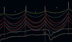
The first step in the design was to address the clearance issues. The original PLS-CADD model for the line was used to verify the extent of the originally identified clearance issues. It was refined during the course of the project to determine the exact placement of the relocated structures as well as to ensure all required clearances and structure capacities remained adequate in the final solution.
Studies determined the existing conductors were sagging below the minimum ground clearance line in some cases. To remediate the clearance issues, the existing towers were relocated and raised by the addition of extensions to provide adequate clearance at the conductors’ final locations.
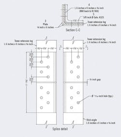
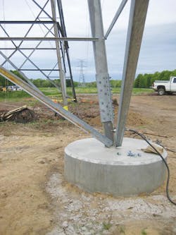
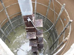
The original tower design used grillage foundations. However, ITC’s current design and construction practices are to use drilled piers. For this new application, the design team modified the original extension leg designs to provide a new splice connection with a new stub angle. The new foundations were designed using LPILE software.
A new splice connection marrying the legacy tower extension legs to the new stub angle was specified by the design team and detailed by the steel fabricator. For the new tower extensions, the design team selected double-shear bolts for the connections between the new tower extension leg and the stub angle, which reduced the number of bolts required by 50%, thereby reducing material cost and field assembly time.
The double-shear bolt connections were achieved by using one inside angle and two 0.25-inch (6.34-mm) outside plates connected with 0.625-inch (15.875-mm)-diameter A325 bolts, which have higher capacity than the existing splice connections. Close coordination between the design team and the steel fabricator was necessary for accurate fabrication. Furthermore, Falcon Steel test assembled the tower extensions at its facility to ensure all pieces fit properly before shipping to the field.
Construction Phase
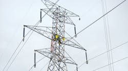
This challenging ITC project had an aggressive schedule for design and construction. A total of 25 existing towers were moved approximately 50 ft (15 m) in line from existing tower locations and raised 10 ft or 20 ft. All the construction work was performed under the direction and supervision of ITC personnel, and the utility selected M.J. Electric to perform the steel erection and all other construction activities associated with the structures, conductors, shield wires and access.
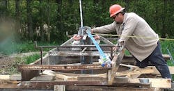
Total Foundations was selected to install the drilled pier foundations and to help ensure proper installation of the hundred foundations required for the project. The design team recognized the importance of providing precise hole-to-hole distances between the stub angles because of their sloped nature. Design, construction and staking personnel worked closely to ensure the foundations were properly constructed. Stub angle fixtures were used to ensure all stub angles were leveled and held at the correct slope.
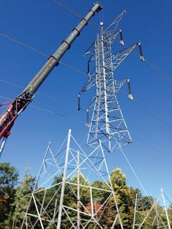
For the physical relocation of the existing lattice towers, two all-terrain hydraulic boom cranes at 275 tons and 350 tons (250 metric tons and 318 metric tons) were selected. Line crews assembled the tower extensions on the ground while the foundations were curing, and the tower extensions were erected on the new piers approximately seven days after pouring the concrete. While the extensions were being assembled and erected, a separate crew disconnected the conductors from their hardware and placed them into rollers in preparation for raising the tower to the new extension.
Lifting points were selected at the horizontal cross-bracing locations to prevent tower member overstress during erection. After removing the connection bolts from the tower legs, tie ropes were used to keep the exiting tower legs relative to each other. Once the rigging, ties and such were in place, the tower was lifted from its original location. The crane repositioned the tower over the newly erected tower extension before all connections of the tower legs to the tower extensions were made and site cleanup was completed.
For maximum efficiency, an assembly-line approach was used to keep every aspect of construction moving. At the peak of productivity, crews were able to complete an average of three towers every two days, with the record being three towers completed in one day. Final restoration and stabilization were conducted at the end of the project.
Informed Decision Making
Minimizing the outage duration, reducing material lead times and managing overall costs were the driving forces behind ITC’s decision to raise — instead of replace — the steel towers along its 345-kV Argenta-Palisades transmission line. The success of this and subsequent projects is a product of ITC’s focus on operational excellence, which guides the development of best practices in the utility industry.
Any utility facing a similar situation can conduct its own evaluation encompassing project options, projected outage time and the overall cost of all the alternative approaches. Following this sound process will enable a utility to make an informed decision.
The success of the Argenta-Palisades line modifications naturally led ITC to consider implementation of the same approach to modifications required elsewhere, as identified during a subsequent North American Electric Reliability Corporation analysis. Over the past six years, the project team has completed four additional 345-kV uprating projects using a similar tower-raising approach.
Ashley DuPree is a professional engineer serving as the supervisor of line design for ITC Holdings Corp. in Novi, Michigan, and has 14 years of experience in high-voltage and extra-high-voltage transmission line design and standards. DuPree holds a BSEE degree from the University of Missouri-Rolla.
Fang Liu is a civil/structural engineer with more than 25 years of experience in structural analysis and design. His experience includes industrial, institutional, commercial projects and power plants. Most recently, Liu has specialized in analyzing lattice towers for transmission line projects.
Jonathan Rumble is a civil/structural engineer with 10 years of experience working on transmission line and substation projects.
Ricardo Ortegon is a civil/structural engineer with more than 22 years of experience in engineering design and project management. For the past 14 years, he has been focused on power delivery, specifically transmission line projects.
