Testing Ground Level Distribution Systems
Key Highlights
- GLDS encases medium-voltage cables in conduits within an anchored rail system and protective geopolymer concrete.
- Repeated vehicle tests caused no damage to conduits, plates, anchors, or the reinforced concrete encapsulant.
- Reinforced geopolymer concrete withstood substantially more falling-weight impacts before cracking or requiring repair than Portland cement concrete.
- In more than 20 controlled ground-fire events, the plates did not sustain combustion and conduit temperatures rose by no more than about 1.5°C.
- Ampacity is comparable to buried conduit for much of the year, though peak-summer conditions may require location-specific derating.
Recent work examining the effectiveness of various technologies used to improve resilience and wildfire performance has shown that utilities rank placing lines underground in the top two approaches.
Across the utility industry, this has led to undergrounding as one of the main preferences. However, the locations chosen for wildfire mitigation, public safety, and right‑of‑way often means that conventional trenching is slow, expensive, or simply impossible.
Rocky terrain, contaminated soils, and environmentally sensitive corridors are just a few of the complicating factors which can push excavation timelines and costs far beyond those typically seen.
Ground‑Level Distribution Systems (GLDS) provide a solution to the complicating factors of terrain by challenging the long‑standing assumption: that underground cables must always be buried deep to be protected. Instead of relying on burial depth for protection, GLDS provides the same performance with layers of engineered mechanical protection (NESC Rule 352D) allowing medium‑voltage (MV) cables to be installed at or near the surface.
What Is GLDS?
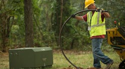
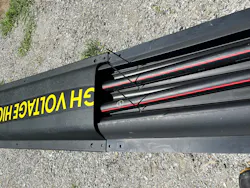
A GLDS installation places MV cables inside conduits, usually in the form of Cable in Conduit (CIC), that are restrained within a plastic sectional rail system, anchored to the ground. A flame‑retardant thermoplastic top and bottom plate form the outer protective envelope into which an engineered geo polymer concrete is poured to fully encapsulate the conduits
A closely related variant, the Minimum Cover Distribution System (MCDS), uses the same structure coupled with a shallow burial within the topsoil when limited cover is preferred in cases such as roadway crossings or aesthetics or capacity. This embodiment supports flexible depths (typically around 6 - 15 inches) and does not require excavation of the subsoil.
A number of early field pilots at DTE / EPRI / PG&E have demonstrated the constructability of the concept, however constructability is not the only important question that utilities are asking: these questions include Will a surface‑installed system survive real‑world abuse? Will cables within GLDS operate differently to conventional direct buried approaches.
Purpose‑Built Testing
To answer these questions, EPRI and its utility collaborators constructed a number of full‑scale GLDS installations at its Lenox Laboratory. These were designed specifically for engineering and scientific research rather than demonstration. Testing focused on 2nd Generation GLDS, incorporating high strength, water free, geopolymer concrete and non‑metallic rebar to improve impact resistance and durability.
The testing program evaluated four primary risk categories utilities worry about most:
- Vehicle traffic
- Falling‑weight impact
- Ground fire exposure
- Thermal performance and ampacity
Vehicle Impact
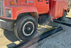
One of the most visible concerns with the surface installation of GLDS is the increased potential exposure to vehicles, particularly in roadside and right‑of‑way installations In testing, GLDS sections were repeatedly driven over by vehicles ranging from pickup trucks to heavy transmission utility trucks weighing more than 17 metric tons.
The reinforced GLDS sections showed:
- No damage to the cable conduits
- No damage to the plastic top plates or anchors
- No cracking or loss of function of the geopolitical polymer concrete encapsulant
- No conduit distortion under repeated direct and glancing impacts
Analysis of cumulative loading suggests that even very heavy vehicles would need to strike the same location many times before damage would be expected—an unlikely real‑world scenario.
Falling‑Weight Impact
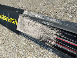
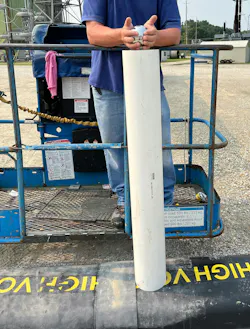
To simulate dropped tools, debris, or tree strikes, EPRI developed a repetitive falling‑weight test using a 9‑kg steel sphere dropped from 1.2 meters onto the same point on the GLDS structure. The results clearly differentiated encapsulation materials.
- Reinforced geopolymer concrete required roughly two dozen impacts to initiate cracking and more than 40 impacts before repair was needed
- Traditional Portland cement concrete, such as that used in conventional duct banks cracked in as few as two impacts and required repair after roughly ten
The takeaway for utilities is straightforward: not all concrete performs the same, and reinforcement strategy is critical when burial depth is removed.
Wildfire Exposure
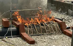
Wildfire mitigation is one of the strong drivers for undergrounding through the reduced chance of vegetation ignition. However, wildfires may interact with a GLDS installation; testing addressed this survivability directly. At Lenox, GLDS sections were subjected to controlled ground‑fire events (>20) using straw and wood fuel loads representative of dry‑season conditions.
Key findings included:
- Flame‑retardant top plates did not ignite or sustain combustion
- Geopolymer concrete encapsulant showed no degradation - unlike conventional concrete the absence of structural water avoids thermal spalling
- Conduit temperatures increased by no more than ~1.5 °C, even after repeated burns - due to the thermal properties of the geoploymer concrete
Thermal Performance and Ampacity
Unlike a typical direct buried configuration, where heating comes only from the conductor, cables within GLDS are exposed to additional energy input from solar radiation. Moreover heat transfer is impacted by the ambient air temperature rather than the more usual ground temperature. Extensive thermocouple instrumentation on cables within the conduits at Lenox measured temperatures at the conductor, conduit, encapsulant, and top plate under real environmental conditions.
Results showed that:
- GLDS ampacity is influenced by ambient temperature and solar irradiance and this is highly location specific
- For much of the year, ampacity is comparable to conventional buried conduit installations During peak summer conditions, some derating may be required, depending on location
Opportunities for Deployment
Based on the testing and early utility deployments, it is believed that GLDS is well suited for:
- Wildfire‑prone corridors where trenching is impractical
- Rocky or contaminated ground
- Environmentally or archaeologically sensitive areas
- Temporary or rapidly deployable urban MV circuits
- Substation environments where excavation disrupts grounding systems
From Test to Field
Phase I testing at Lenox confirms that modern GLDS designs are mechanically robust, fire‑resistant, and electrically viable when properly engineered. It is anticipated that ongoing research will address performance in minimum cover applications, long‑term aging, freeze‑thaw exposure, cable jointing and multi‑phase magnetic fields, but the evidence to date supports broader pilot deployments.
There is little doubt that GLDS represent an expanded capability and shift in mindset for utilities facing growing pressure to underground faster and with less disruption: engineered protection can substitute for excavation depth when the performance is proven by testing.
Acknowledgments
This article was also prepared with the contribution of Connor Duffy, PPL; Louie Mercurio, SCE; Marizol Perez Cruz, SDG&E; and Henry Wilson-Sowah, CHE.
About the Author
Nigel Hampton
Nigel Hampton is a Technical Executive in the Underground Cable and Wildfire spaces within EPRI. Nigel has more than 35 years of experience spanning utility, manufacturing, standards, and R&D organizations with technical interests spanning cable diagnostics, asset management, reliability, wildfire mitigation and underground distribution systems.
Adam Jacob
Adam Jacob is a Principal Engineer with DTE Energy. Adam has approximately 28 years of utility engineering and power-system experience. Technical interests include distribution engineering, grid reliability, underground systems, and utility asset performance.
Margaret Kaye
Margaret Kaye is an Engineering Supervisor in Overhead Standards and Planning with Con Edison. Margaret has over 5 years of engineering, utility, and research experience. Technical interests include power systems and utility standards.
Roozbeh “Rudy” Movafagh
Roozbeh “Rudy” Movafagh is Vice President of Engineering and R&D with Energy Connect Corporation. Rudy has more than 30 years of utility engineering, product-development, and technology-innovation experience. Technical interests include ground-level distribution systems, infrastructure innovation, and resilient power delivery systems
Saad Syed
Saad Syed is a Principal Program Manager, Asset Strategy with Pacific Gas & Electric. Saad has more than 15 years of experience leading engineering, asset-management, technology, and utility-innovation programs. Technical interests include asset strategy, grid modernization, and utility technology deployment.