Based on Southwire Company’s CableTechSuppportTM Services records from the past five years, the number-one challenge in underground electric systems occurs before energization, due to unforeseen damage during transit, storage, handling, installation, terminating, splicing, or testing. The number-two issue is related to severe environmental or weather exposures causing excess stress on cable systems and triggering premature failures. The number-three concern is aging or outdated assets including cables, accessories, protective equipment, and monitoring devices.
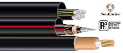
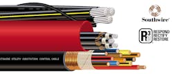
Southwire Company’s Re3TM Consultation Services provide emergency response to rectify field problems, to restore electrical systems, to minimize project delays and to shorten power outages. The following are three engineering service examples that Southwire Company, LLC recently delivered to utility owners or contractors.
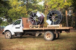
Respond: Water Intrusion Support & Nitrogen Purging Services
Aluminum or copper materials, in general, have a good resistance against mild corrosions. However, the dielectric breakdown strength (Volts per mil or kV per mm) of any insulation material under a wet condition or thermal cycling could be reduced by up to 50% compared to that in a dry state. Thus, to mitigate water intrusions during cable transport and installation, the most common practice is to seal the exposed cable ends with either a cold shrink end cap or a heat-shrinkable end cap with the internal wall coated with hot-melt adhesive to bond to the cables. This is the standard practice for medium- and high-voltage cables before the products depart from the manufacturing facility. Once the end caps are removed for cutting, terminating, or splicing, installers should reseal the ends and ensure that the cable is not placed in a location or a position where the ends can be submerged under water. It is also important to inspect the cable assemblies for water migrations and allow any trapped moisture to dry before installing terminations or joints.
Medium-voltage or high-voltage power cables designed with water-blocking components, such as a strand-fill compound, water-blocking powder or a water-swellable tape, are less likely to suffer from major water damages, extending far into the cable end. However, for low- or medium-voltage cables without any water-blocking component, there are several remedies to remove trapped moisture. The most effective technique is nitrogen purging using a pressurized tank. Using compressed nitrogen instead of air — which might contain moisture — can minimize oxidation and ensure a more consistent control of purging pressure. Connecting the wet conductors first, and then the cable with dry nitrogen gas under low pressure to flush out the water, has proven to be successful in the field.
During the frigid winter months when the ambient temperature is below freezing, applying an electrical heating sleeve or blanket over the cable jacket to melt any ice is a prerequisite before purging. In addition, a heating blanket over the cable on a reel could take a long time to melt any ice in the cable. Depending on the conductor size, degree of water exposure, cable routing or lengths, and ambient conditions, it could take from a couple of hours to several days to complete the moisture removal process.
Special attention needs to be paid to cables that have been exposed to hurricanes or other storms. During major weather disturbances, contamination from the surrounding environment, including fertilizers, pesticides, corrosive chemicals, hazardous waste, rusts, or metallic fragments, may leach into flood waters. These pollutants can alter the pH of the water, thus initiating galvanic corrosion of exposed aluminum and copper conductors, neutrals, metallic shields, bare drain wires, electrical grounding conductors, as well as connectors or cable clamps. Polluted water can permeate dielectric materials that have a Water Vapor Transmission Rate (WVTR) that is highly dependent on the chemical family of the material and its temperature. The greater the conductor’s operating temperature or the higher the ambient temperature, the faster the moisture migration will be through the dielectric material. Ionic-rich acidic or alkaline water may attack the dielectric material, which, in turn, reduces the capacitance, increases the leakage current, and, ultimately, causes dielectric breakdown or a reduced cable life. The damages to the electrical systems from the contaminated water can take a long time to occur. However, it might be an imminent threat on an already aged cable assembly.
When metallic shielding or copper wiring are exposed to moisture, they may discolor due to oxidation or corrosion, and the bright metallic appearance may become black, green, reddish brown, depending on the copper oxide layer formed on the surface. It is recommended before making connections to use a brass brush to remove the oxidized layer, followed by a thorough rinse with a cable cleaner or a lint-free cleaning wipe. Brushing and cleaning reveal a renewed copper surface and create a highly conductive path with the lowest possible electrical contact resistance. An electrical contact with an oxidized interface will overheat at the connection point and cause premature splice failures, for example.

Rectify: Ampacity Derating Validation and Electrical Modeling Services
The most frequently requested design parameter for utility and renewable cable systems is ampacity or current rating. Ampacity is the maximum current carrying capacity of a specific cable or assembly with a defined routing and a unique installation. A cable may have ampacity values associated with free air, direct burial, conduits, duct banks, and cable trays, each of which will be different. Many factors such as burial depth, adjacent heat sources or other cables, soil thermal resistivity, backfill compaction, layout of the multi-circuits, bonding schemes, conduit materials, and ambient conditions play a critical role in determining the true current rating. A combination of different parameters could derate the cable by as much as 50% when compared to the general ampacity values published in industry standards, such as IEEE Standard 835, ANSI/ICEA P-117-734, or NFPA 70 NEC. Therefore, ampacity is not a single-valued attribute of a given cable type, but rather, a custom-driven data that must be calculated or validated cautiously for every unique project. One should always choose the worst section of a cable run to represent the value for the entire circuit.
Underground cable ampacity is influenced by five major parameters: the conductor size or type, soil thermal resistivity, direct burial versus conduit installation, bonding method, and the load factor. Doubling the conductor cross-sectional area or doubling the number of conductors will not double the rated current. Either a rocky terrain or soils rich in organic matter will reduce thermal conductivity and decrease ampacity up to 40%. System operating conditions and procedures may dictate the type of bonding that is used. A two-point metallic sheath bonding configuration may reduce the ampacity by about 20% when compared to the single-point bonded method. The impact of the grounding procedure on the ampacity is more significant on larger conductor sizes. A direct buried method supplies an ampacity that is 15% to 25% greater, depending on the soil thermal resistivity, than a conduit installation, as the soil can dissipate heat more efficiently than the air surrounding the cable in a duct.
Medium-voltage cables rated up to 46 kV for utility projects are typically operated at a normal maximum operating temperature of 90 oC with a load factor less than 60-70%. However, for data center operations or certain heavy-duty commercial facilities, some of the power cables could operate close to 105 oC continuously with a load factor up to 75-85%. Extra care needs to be taken to prevent overheating as the cable accessories might not have been tested to withstand long-term thermal cycling at elevated temperatures. It is crucial for end users to confirm that all the cable connectors and accessories have been qualified for 75, 90, or 105 oC when pairing them with secondary or primary underground cables. Furthermore, utilizing custom ampacity modeling results instead of ampacity tables to select the best conductor size can prevent thermal runaway and minimize premature cable failure.
Restore: Cable Replacement Designs and Services Due to Upgrading, Aging, or Overloading
Long-term performance of underground cable systems is influenced by many variables including, design, quality of terminations and splices, operating conditions, and the environment. All factors should be evaluated to ensure that the best design is chosen for each specific application. No scientific principle or test method exists in the industry to determine the true life expectancy of any transmission or distribution underground cable assembly. However, wires and cables that are produced today should last 40 to 60 years as expected by utilities provided the cable and its accessories are designed, manufactured, installed, protected, and operated properly.
In case of sustained overloading or overheating, for example, due to unforeseen winter storms or other severe weather events, a diagnostic protocol, such as Insulation Resistance (IR), Partial Discharge (PD) or Very Low Frequency Tangent Delta (VLF TD), can be deployed in the field to help assess the condition of an aging cable and its accessories. If it is determined that the cables have exceeded their useful service life, then prompt cable replacements should take place to prevent extended power outages.
Upgrading cables to accommodate future grid expansions, such as a higher voltage, a greater load factor, or an enhanced short circuit current capacity, has become very common. It is also a good practice to add safety margins to the cable design and consider potential environmental risks, such as corrosive soil and frequent flooding. Distribution systems with line voltage ratings of 5, 15, 25, or 35 kV commonly supply power to residential neighborhoods in the United States. A 15 kV rated primary underground cable is widely used by North American utilities since it is suitable for any line with a 15 kV class voltage, including 12.47 kV, 13.2 kV, and 13.8 kV.
We have seen a steady increase in distribution line upgrades from 15 kV to 25 kV or 25 kV to 35 kV in the past decade with more utility standards requiring the thicker 133% insulation level compared to the 100 % insulation wall thickness. The cable insulation level is dictated by how fast the protective equipment can de-energize the electrical line in case of a fault. If a fault can be cleared rapidly within 60 seconds with a good relay protection, then a 100% insulation level is sufficient per the industry standards, such as ANSI/ICEA S-94-649 or ANSI/NEMA WC 74/ICEA S-93-639. However, if a fault will sustain beyond 1 minute, but less than 1 hour, then a 133% insulation level is required.
In addition to fault clearing time and protective equipment, one might want to consider the effect of the insulation on the stress of the dielectric material. Raising the insulation wall thickness from 100% to 133% decreases the electrical stress significantly and potentially extends cable life. The highest electrical stress point is located at the conductor shield and insulation interface. A 15 kV 1/0-19 AWG cable with a 100% insulation level generates an electrical stress of 2.7 kV/mm at the conductor shield and insulation interface compared to that of 1.4 kV/mm at the insulation and insulation shield interface. A 25 kV 1/0-19 AWG cable with a 320-mil (133%) insulation wall yields a 15% reduction in electrical stress at the conductor shield and insulation interface compared to the same conductor size with a 260-mil wall (100%). A 35 kV 750-61 kcmil cable built with a 133% or 420-mil insulation wall generates a 16% reduction in electrical stress at the conductor shield and insulation interface compared to the same conductor size with a 100% or 345-mil wall. The smaller the conductor size, the greater the impact of the insulation level on the electrical stress at the same voltage rating. A low-stress cable design might be necessary for larger feeder cables that are powering critical infrastructure facilities or are installed in a location prone to electrical surges.
In conclusion, many complex factors contribute to intelligent undergrounding. Southwire Company, LLC provides Re3TM Consultation Services to respond, rectify, and restore utility networks and offers a variety of custom wire and cable solutions that are reinforced or resilient to deliver the most reliable electric grid in North America and beyond.
Sponsored by: