Adapt Line Protection For Wind Integration
Key Highlights
- Inverter-based wind turbines behave differently during faults, limiting fault current and complicating traditional protection schemes.
- Zero-sequence voltage is a reliable polarizing quantity for directional elements, whereas negative-sequence quantities are less dependable in inverter-based resources.
- Adjustments such as increasing fault detector thresholds and disabling certain differential elements help prevent false trips while maintaining protection coverage.
- Communication-assisted schemes enhance protection dependability, especially under low-wind or no-wind conditions, by integrating phase and ground distance elements.
- Utilities should audit existing protection settings, leverage transient modeling, and develop staff expertise to effectively integrate inverter-based renewable resources into the grid.

The February 2021 Texas winter storm left more than 4.5 million customers without power, causing at least 246 deaths and an estimated US$300 billion in damages. While inadequate winterization was a central factor, the crisis underscored another challenge. As renewable generation expands, conventional protection schemes require fundamental adjustments.
Wind power has become a cornerstone of the U.S. generation mix, with more than 150 GW of installed capacity. For the first time in April 2024, wind generation surpassed coal-fired generation for two consecutive months. These resources rely on power electronic converters that behave differently from synchronous machines during faults, challenging the assumptions built into traditional line protection.
When a major utility connected a large wind farm to its 345-kV transmission system, its protection engineering team faced a critical question: Would their existing relay settings provide secure and dependable protection? System studies revealed the answer was no. The engineering analysis that followed examined the protection challenges encountered during this process and the solutions that worked.
Conventional Settings
Modern wind farms use two main turbine types:
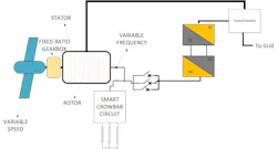
- Type 3 turbines (doubly fed induction generators) are partially decoupled from the grid and include crowbar circuits that activate during severe faults. When the crowbar activates, the turbine behaves like an induction generator. When inactive, behavior is determined entirely by converter controls, which vary among manufacturers.
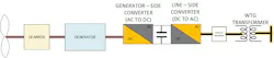
- Type 4 turbines use full-scale converters that completely decouple the generator from the grid through a direct-current link. Their fault response is determined by proprietary control algorithms that vary significantly among manufacturers.
Both types act as current-source inverters under fault conditions. Unlike synchronous generators, where fault current magnitude depends on the impedance between the generator and the fault, wind turbine fault current is limited by converter controls and is typically capped near rated current, making it much less dependent on fault location. This fundamentally changes how protective relays perceive system faults.
The protection team of the utility looking to connect a large wind farm identified several specific concerns in their assessment. Convential protection elements assume homogeneous voltage and current frequencies but inverter-based resources (IBRs) can inject currents with differing frequency components and phase relationships, potentially compromising security and dependability. Fault current magnitude is limited by converter controls rather than system impedance, and negative-sequence currents are often lower asymmetrical, and unreliable for determining fault direction. Additionally, the phase angle difference between negative-sequence voltage and current is larger in IBRs, and the negative-sequence current may contain frequency components that differ from the negative sequence voltage, further challenging traditional protection schemes.
For transmission line protection, these characteristics meant conventional settings developed for synchronous generation could not ensure both security (avoiding false trips) and dependability (clearing real faults).
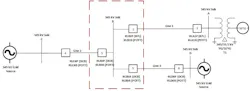
The 345-kV system connected the wind farm to Substation B through Line 1, with Lines 2 and 3 providing connections to adjacent substations. The relays set in this case study are primarily at Sub B. Any reference to normal conditions assumes no line outages and the wind blowing (i.e., all wind turbines in service).
An alternate-normal condition implies no outages and no wind blowing (i.e., all wind turbines offline). A single contingency (N-1) refers to an outage of a 345 kV transmission line that was serving as a source of fault current to the protected line relays on line 1. The existing protection scheme on Line 1 employs a primary current differential relay, with a permissive overreaching transfer trip (POTT) as the backup. Both the primary and backup relays use positive-sequence memory-polarized mho distance elements, with impedance-based polarization using negative-sequence voltage. System studies showed these conventional settings would not work.
Modifications For Wind
The protection team implemented five key modifications to address the challenges of inverter-based resources, including directional element polarization, distance element adjustments, negative-sequence element modifications, line current differential and communication-assisted scheme optimization.
The first, most critical modification involved directional element polarization. Because negative-sequence voltage proved unreliable with wind farm sources, directional elements were configured to use zero-sequence voltage only as the polarizing quantity for all lines. The wind farm’s generator step-up transformer provides a reliable zero-sequence source for ground faults. This approach ensured security of directional elements for reverse faults on Sub B, when the wind farm was the only source of fault current. It also ensured that the same polarization quantities be used at both terminals of the line for the alternative permissive overraching transfer trip scheme. Directional element thresholds were standardized at -0.3 ohms reverse and +0.3 ohms forward across all substations, providing consistency while maintaining adequate sensitivity.
The second modification focused on distance element adjustments. Mho distance elements were retained because their impedance calculations rely on phase-to-phase quantities governed by fundamental circuit laws, making them less susceptible to source characteristics. However, source impedance ratio calculations under various operating conditions showed potential concerns. Zone 1 reaches were reduced according to standard guidelines, and capacitive-coupled voltage transformer (CCVT) transient detection logic was enabled to provide additional security.
Rather than disabling Zone 1 elements entirely under high source impedance ratio conditions, the team increased fault detector pickup from the default 0.5 A secondary to 1.73 times the line’s winter emergency rating. This factor accounted for the conversion between phase quantities and the phase-to-phase quantities used by fault detectors. This approach maintained fast fault clearing while ensuring security when the wind farm feeds the line radially.
A third modification addressed the negative-sequence element. High-set negative-sequence instantaneous overcurrent elements were configured carefully. For line 1 relays at Bus B, the source of negative sequence current are line 2 and line 3, not the wind farm. For the line 2 and line 3 relays at Bus B, under normal and alternative normal conditions, the wind farm was not the dominant source of negative sequence. Therefore, the pickup was set above the fault current seen by relay 2 for a local bus fault (contribution from the wind farm) but below the fault current (contribution from the grid), making the element inherently directional. For lines 2 and 3 the dominant source of negative sequence under normal conditions was not the wind farm. Under a single contingency, line 2 or line 3 are fed radially by the wind farm, making negative sequence a concern. The pickup of the high-set element was set well above maximum wind turbine injection levels. Additionally, a 1.5-cycle to 2-cycle time delay was added to these elements to ride through transients caused by wind turbine control responses, following relay manufacturer recommendations for inverter-based resource applications.
The fourth modification focused on line current differential. Because wind farms can inject unpredictable negative-sequence current under load conditions, the negative-sequence line current differential element was disabled at both line terminals. This prevented potential false operations while maintaining protection coverage through other means. Phase differential pickup was set to cover three-phase and line-to-line faults, while the generator step-up transformer provided a reliable zero-sequence source for ground fault protection through zero-sequence differential elements.
The final modification entailed communication-assisted scheme optimization. The POTT schemes were maintained but with important modifications. The trip equation included phase distance, ground distance and ground overcurrent elements, but excluded directional negative-sequence overcurrent elements because of concerns about reliable directional supervision with inverter-based resources.
Echo logic was enabled in all POTT schemes to ensure dependability under low-wind or no-wind conditions when lines operate radially from the wind farm. Because the generator step-up transformer provides a reliable zero-sequence source, the directional ground overcurrent element provides both speed and security as part of the communication-assisted scheme.
Lessons Learned
Since implementation, the modified protection scheme has operated successfully across all system conditions, including high-wind output, low-wind output and various contingency scenarios. The protection system has provided secure operation with no false trips while maintaining dependable fault clearing.
The experience provides several important lessons for utilities facing similar challenges:
- Directional determination with inverter-based resources — Zero-sequence voltage provides reliable directional determination when protecting lines connected to wind farms, while negative-sequence quantities cannot be relied on for this purpose with inverter-based resources.
- Fault detector adjustments — Adjusting fault detector settings to reflect realistic inverter-based resource current contributions provides a practical alternative to disabling underreaching elements under challenging source conditions.
Protection element performance varies — Not all protection elements adapt equally well to inverter-based resources. Differential elements based on phase quantities performed reliably, while negative-sequence-based elements required significant modification or, in some cases, needed to be disabled. - Communication-assisted schemes — Communication-assisted schemes become increasingly important as inverter-based resource penetration increases, providing the speed and security that conventional distance and overcurrent elements alone may not achieve.
- Wind farm operator coordination — Coordination with wind farm operators proved essential. Understanding control responses, crowbar activation criteria and firmware update schedules helps protection engineers to anticipate potential issues before they affect system reliability. The unpredictable nature of inverter-based resource response means conventional protection philosophies developed for synchronous generation cannot be applied directly without thorough evaluation.
Implement For Success
Utilities connecting wind farms to transmission systems should audit existing protection settings for lines serving inverter-based resources, leveraging available industry guidance as a starting point. Investment in electromagnetic transient modeling capabilities helps to capture vendor-specific inverter-based resource behavior under various operating and fault conditions. Communication-assisted protection schemes should be implemented where conventional distance and overcurrent elements face limitations. Staff expertise in inverter-based resource protection characteristics should be developed through training and industry collaboration.
The protection engineering community has successfully navigated major grid transformations in the past. The current shift to inverter-based generation represents another significant challenge. As inverter-based resource penetration continues to increase, protection engineers must maintain expertise that encompasses both conventional source behavior and emerging inverter-based resource fault characteristics to ensure grid reliability during this transition.
About the Author
Sneha Vasudevan
Sneha Vasudevan ([email protected]) is a licensed professional engineer with expertise in power system protection and renewable energy integration. She spent a decade at Schweitzer Engineering Laboratories specializing in relay coordination and transmission line protection. She currently works at Uplight Inc., a clean energy technology company. Vasudevan serves as Chair of the IEEE San Francisco Women in Engineering Affinity Group.