Increase Reliability in the Power Grid and Reduce Wildlife-Related Fire Risk
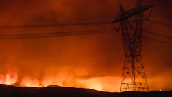
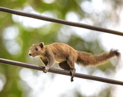
Localized fires caused by the interference of animals (such as birds, squirrels, raccoons, possums, bats, rats, snakes, and more) with high-voltage overhead lines and substations — and the uncontrolled wildfires that can result on the ground below — is an increasingly common problem for electric utilities and industrial power-distribution systems all over the world. Such problems are particularly common in older networks, which were typically designed with few protections against wildlife-related outages or fires. Up to 25% of the fires associated with power-distribution systems are preventable with the appropriate engineering controls, and are most commonly caused by the following:
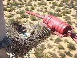
- Wildlife-related activities, including ignition nesting materials and other animal-related debris, pole-top fires of electrocuted birds and animals falling to the ground, igniting dry vegetation below
- Flashover of pollution (such as bird guano and airborne environmental pollutants) that has built up on insulated components. Such materials can create a conductive path for current to flow through, increasing the risk of arcing, flame tracking and flashover
- Vegetation-induced fire resulting from live bare conductors clashing with dry vegetation
- Conductor clashing, where two adjacent conductors come in contact with each other, generating sparks, conductor damage and travelling arcs
Fire-Related Outages Caused by Wildlife & Vegetation
In general, fire-related outages caused by wildlife and vegetation are categorized in two categories; both types of risk can be mitigated with the addition of appropriate insulated Wildlife Asset Protection (WAP) components:
- Phase-to-earth faults. These occur when the presence of wildlife or debris forms a conductive pathway that connects the equipment phase to the ground
- Phase-to-phase faults. These occur when two adjacent phases collide or are momentarily connected via wildlife or debris (for example, during wire-clashing incidents), producing hot, molten metal particles that can ignite dry materials nearby.
Proper material selection is an especially critical — and often-overlooked — effort to upgrade overhead lines and substations with insulating components to help reduce ignition risk and prevent wildfire propagation. If careful consideration is not given to selecting the most appropriately formulated engineering polymers for these insulated components, they can still be susceptible to ignition and fire propagation. This is discussed in detail below.
This article discusses a variety of retrofittable solutions — and the importance of following an overall engineering design strategy that includes thoughtful consideration of material properties and their impact on component performance. Utility owners and operators planning upgrades to reduce wildlife-related risks should keep the following in mind:
A) Any retrofittable solution should be designed to match the lifetime expectancy of the asset being protected. For example, substation transformers and switchgears are usually designed for >35+ years of service life.
B) Quality insulating components designed for stable operation over their projected lifetime will help reduce or even eliminate fire threat in their overhead power lines and substations. Materials that deteriorate prematurely over time will create new problems in the future.
If appropriate engineering design upgrades are not underpinned with robust material selection, utilities risk undermining their own efforts to safeguard the critical assets and eventually, components manufactured from materials that are prone to early degradation will fail and efforts to ensure protection will be lost. It should be noted that the electrical and mechanical performance of new and aged materials are very different. It is critical to test aged samples in order to predict lifetime. For example in the TERT test, abraded samples should be evaluated per ASTM D2303 STEP test method.
The Business Case for Installing the Right Insulation Upgrades
Too often, the investment needed to reduce the risk of wildlife-related fire and wildfire risk are deemed discretionary, and such investments tend to be reactionary. This operating philosophy is dangerously short-sighted, as wildlife interactions with overhead lines and substations are unavoidable and create consequences that exact an enormous toll on the company and surrounding community.
Utility owners and operators — and industrial operators that own and operate captive power-generation systems that involve overhead lines and substations — should consider the strong business case that exists for making timely, appropriate investments in appropriately formulated insulating components, especially those that provide a strong overall emphasis on prevention.
Efforts to improve fire safety and enhance operating reliability provide demonstrable payback for utility owners, by helping them to avoid the costly and catastrophic implications of wildlife-related fires, including:
- Human injuries and loss of life
- Damage to (and loss of) power grid assets
- Service interruptions and power outages, which can threaten not only individual homes and communities, but create potentially hazardous conditions at hospitals, industrial facilities, schools and more
- Environmental hazards and potentially life-threatening danger to personnel if the wildfires are able to impact nearby industrial facilities and result in a loss of potentially hazardous materials to the environment
- Catastrophic damage to agricultural and horticultural assets
- Regulatory repercussions related to penalties, fires and litigation
- Negative media and social media attention creating reputational damage and damage to shareholder value
Threats posed by wildlife are both real and pervasive. By one estimate, 900,000 to 1.4 million migratory birds are electrocuted annually on electric distribution lines in the U.S. alone.
Animals are involved in 6-to-7% of outages in the distribution network in Australia. The number of outages caused by animals is increasing - and that increase specifically is related to the recent arrival and rapid growth of a Grey-Headed Flying Fox colony. Birds are responsible for two-thirds or 4%, possums 1% and bats 1%. The balance is attributed to rats, termites, snakes and lizards.
Fire in the Distribution System at a Solar Farm in California Has a Loss in Revenue of $8-9 Million
In one example from June 2019, a fire in the distribution system at a solar farm in California resulted in 1,127 acres lost to wildfire, and a loss of 84% of its generating capacity, with a loss in revenue of $8–9 million. The incident was caused by a crow that had flown between adjacent live phases, bridging the wires and thus creating a circuit. The bird was electrocuted, its wings caught fire and when the carcass dropped to the ground, it ignited the dried grass below.
And wildlife-related events can create profound financial penalties for electric utility owners. For example, the U.S. Fish and Wildlife Services (FWS), via the Migratory Bird Treaty Act, makes it illegal for anyone to kill a protected bird by any means without obtaining a permit. The Agency has fined multiple North American utilities over the past 20 years, with fines and penalties for killing eagles and other protected birds of up to $10 million.
A possum caused a power outage to 12,000 homes and businesses in Sydney, Australia when it came into contact with two live parts of the electricity network near a large substation. According to the utility spokesperson, “There are a lot of possums in Sydney and they use the power lines as their own highway - as a connection between trees or roads”
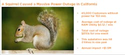
For most utilities, the ability to avoid even one potential outage can help to underwrite the costs to upgrade the system with appropriate protections (See FIGURE A).
Utilities Must Manage Parallel Risk Factors
In addition to managing the risk associated with wildlife interactions, utility owners and operators must also contend with other persistent risks that arise from a confluence of complex factors. These include the following:
Weather Severity; Regional and Seasonal Weather Patterns
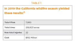
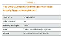
Over the past few years, pervasive wildfires in California, Australia and elsewhere have produced tragic headlines and profound personal and financial impact on communities, businesses, wildlife habitats and utility and industrial infrastructure. Weather extremes result in dry vegetation, which increases the risk that localized, spark-induced fires will be able to rage out of control in an instant. Recent statistics are sobering. (See table 1 & 2 ~ fire statistics from CA and Australia)
Aging Electric Utility Infrastructure
Many privatized utilities have underinvested in their extensive legacy infrastructure for years or even decades. As a result, these aging systems are facing new challenges every day, from mounting threats posed by severe weather to aggressive new reliability targets and increased customer demand.
Traditional options for upgrading aging infrastructures to reduce fire risk are not feasible in many locations or would be prohibitively expensive (this includes burying conductors). Similarly, replacing conductors with covered conductors is an option, but would be relatively costly.
Fortunately, today’s utility owners have many engineering options available to them, to install affordable upgrades to their overhead lines and substations. Such efforts involve installing selective upgrades to targeted, high-risk areas. By installing insulating solutions to both thwart wildlife interactions with overhead lines and substations, and actively prevent ignition and fire propagation, utility owners have a more-economical option to mitigate fire risk. With strategic engineering investments, the influence of wildlife on outages and fires can be avoided.
Sadly, too many operators still view such investments as discretionary. Such a short-sighted approach to design, operation and maintenance of critical power-distribution assets has proven to have costly and catastrophic consequences.
Equipment Failures
Most capital equipment installed in a power utility network is designed to have a functional service life of 35+ years. In reality, most utility infrastructure components remain in service until failure (which could be in excess of 40–50 years). As equipment components age and come to the end of their useful life, they often become harder and more costly to clean, maintain (and they are often to blame for costly power outages). Thus, upgrades to replace obsolete components finally becomes a more cost-competitive approach.
Making matters worse, in many cases, the drive to reduce costs results in selection of less-expensive equipment that provides shorter life spans and increased maintenance costs to maintain the components safely and reduce fire risk. Given the persistent and growing risk of fire faced by today’s utility owners, relentless prioritization of cost-cutting efforts over sound engineering and material science design principles often prove to be “penny wise but pound foolish,” as the old adage goes.
Material Failures
As noted above, capital equipment in power-distribution systems is typically designed to last >35 years or more. It follows that any ancillary protective equipment installed to protect the capital assets should also be designed to provide a functional life for the same duration.
Properly specified insulating components can be selected to help reduce fire risk in overhead lines and substations and match the lifespan of the other assets they are designed to protect. During selection and specification, close consideration must be given to selecting polymeric formulations that can withstand the harsh operating conditions most overhead lines and substations routinely experience — characterized by high-voltage stress, pollution buildup, pollution-induced arcing, flashover, elevated temperatures and mechanical stress.
Utility owners should partner with vendors that have a long, proven track record, a broad product portfolio, and a deep bench of expertise in electrical, mechanical and materials science..
For examples, insulated components that are not manufactured from the most appropriate performance polymer face gradual degradation over time, have elevated risk of tracking, embrittlement due to ultraviolet (UV) damage, melting due to poor thermal resistance, and ignition due to poor arc resistance of the aged surface. All of these pervasive risks can be reduced or even eliminated with proper component and material selection.
Pollution Buildup and Secondary Ignition Sources
Guano from animals and salt buildup in coastal areas (and even airborne pollutants from industrial and environmental activities) can wreak havoc on many engineering polymers. Such pollutants routinely accumulate on the surface of insulated components during long, dry periods, and then washes away with rainy cycles. However, at the end of any dry period, when temperature starts to drop, dew can form on insulation and this combination of conductive contamination and moisture will cause an increase in resistance leakage current and localized arcing on the surface of the insulation. If the material is not engineered correctly, this activity can degrade the material and can lead to tracking over time.
If the insulated component was not specified in an engineering polymer that is explicitly able to withstand pollution buildup, then persistent arcing can degrade the material surface, eventually leading to breakdown and an increasing risk of further buildup, sparking and fire ignition over time.
Mechanical Stress, Abrasion and UV Degradation of Critical Components
As noted, high-voltage overhead power lines operate for decades at a time in direct sunlight and harsh polluted environmental conditions. Long-term exposure to UV can lead to roughening, hardening, thinning, embrittlement and degradation of insulation and critical components manufactured from engineering polymers. Premature failure of insulated parts and other polymeric components puts the entire system at greater risk of ignition, flame propagation and uncontrolled wildfires.
Material Considerations for Insulating Components
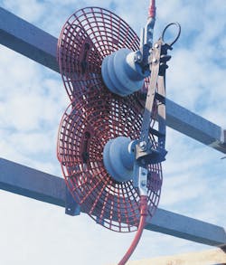
Despite the best intentions, it is impossible to keep wildlife away from the overhead lines and substations that make up a power-distribution network. Instead, such systems must make strategic investments and install the right mix of standard and customizable insulating covers, barriers and guards, to reduce the risk of fire related to wildlife climbing, birds landing, bird nests and other debris, conductor clashing, and vegetation clashing with bare conductors.
As noted earlier, insulating components are manufactured from engineered polymers, but not all polymers are able to guarantee the same type of fire protection — and, importantly, the level of fire prevention that is essential — to effectively mitigate actual fire risk. Paying close attention to the material science considerations and formulation options can provide additional advantage when utility owners specify insulating components to safeguard and fortify their high-voltage power-distribution systems. Such components must be designed to withstand damage during decades of exposure to electrical stress, UV degradation in outdoor conditions, power arcs, surface arcing, flame tracking and erosion.
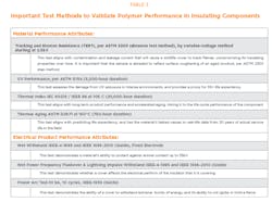
Toward this end, the three most critical material science performance attributes the utility owner should consider when specifying insulating components are these:
Tracking and Erosion Resistance (TERT). TERT provides a measure of a material’s tracking resistance, which is its ability to withstand surface arcing and ignition under high stress environment. If the material properties of the insulating component do not have a sufficient TERT rating, arcing can lead to material deterioration which can lead to ignition, exacerbating the risk of starting a wildfire in dried vegetation on the ground down below.
A material’s TERT rating can be demonstrated using the ASTM D2303 (abrasion test method) (2.5–3.25-kV). This is a destructive, variable-voltage test method that brings a material to failure to demonstrate ability to withstand erosion, tracking and fire. A polymer’s TERT rating and tracking resistance provides a critical indication of the material’s ability to maintain its functional and mechanical integrity in the face of high voltage incidents, pollution flashover and power arcs over time.
The ASTM D2303 (abrasion test method) was developed to simulate surface arcing. This test measures a materials’ life expectancy under stress in terms of time to failure (minutes) at a particular pollution level and kV stress. Using the ASTM D2303 (abrasion test method), every tested material will eventually fail, it is just a matter of time to failure in the face of increasing kV stress and exposure to pollution. Sample preparation involves abrading the surface of the test sample to simulate the effects of long-term aging.
It is widely accepted in the industry that the electrical and mechanical performance of aged materials can deteriorate over time. Abrading the surface of the TERT sample (which simulates the roughening of a material due to UV) is a good method to predict performance of an aged material.
Polymeric materials that exhibit insufficient tracking resistance (according to TERT), tend to perform poorly under harsh operating conditions of high-voltage power lines, and thus present a higher risk of longer-term degradation over time, which leads to insulation breakdown, increased spark production, flame propagation.
Ultraviolet (UV) Resistance. UV resistance provides a measure of a polymer’s ability to withstand damage and failure over time from prolonged UV exposure in outdoor environments. Polymeric components that have poor UV resistance are directly implicated in fire risk, as sun damage to plastic components can lead to mechanical degradation and surface roughening over time which makes it easier for environmental pollutants to accumulate (thereby increasing the risk of arcing, tracking and ignition associated with pollution build up).
UV resistance is demonstrated using the ASTM G154, (UVA and B) test method at a minimum test duration of 1,000 hours. However, as a better predictor of UV performance over a 30+ year lifecycle, users of insulation should consider polymers that have been UV tested for 5,000 hours or more.
Thermal Endurance. A polymer’s thermal endurance rating provides a measure of a material’s ability to maintain its mechanical integrity (that is, to resist melting and deforming) in the face of sustained elevated temperatures, This functional attribute is a good predictor of a polymer component’s ability to maintain a long-term service life in the face of elevated temperatures, and the ability to withstand melting and dripping also helps to reduce risk (as hot plastic dripping on dry vegetation below can trigger a wildfire).
Thermal endurance on insulating covers is typically demonstrated using two test methods:
A. Thermal Index IEC 60216/ IEEE 98 at 105°C (221°F), which demonstrates a material’s thermal performance for 20,000 hours, and
B. Thermal Aging ASTM D2671 750 hours at 150°C (302°F), which is a useful indicator of life expectancy and ties the material’s tested performance attributes to a service life of 30 years or greater
It is critical that utility owners looking to select and specify insulating components manufactured from polymers choose specific polymers that have been formulated with the most appropriate fillers and additives, to ensure adequate performance in TERT resistance, UV resistance and thermal endurance. All polymers will eventually be susceptible to light surface erosion over time (which can be considered a slow, safe and predictive method of aging, allowing operators to eventually maintain or replace affected parts). But the choice of engineering polymer can drastically improve erosion resistance, and this helps to reduce the risk of pollution buildup and fire risk, while extending the useful life of the insulating component. This design philosophy is particularly critical in the high-voltage environment of overhead power lines and substations.
The Scientific Challenges with VO Polymers
In recent years, some utility owners have chosen to install insulating upgrades that favor polymers that demonstrate the flammability classification VO. These are polymers that have some ability to self-extinguish over time once the ignition source has been removed, as demonstrated by the UL94B test methodology.
Polymers that demonstrate self-extinguishing properties have a valuable role to play in certain industries, such as enclosed automotive, industrial and rail applications. In these applications the material itself is not the likely fire ignition source, the source is almost always an external factor but for safety reasons it is important that the materials will self-extinguish and not emit toxic gasses in an enclosed fire zone.
However, polymer formulation for HV utility applications is complex due to the many stresses that such materials must endure during decades in service. Such materials must withstand degradation in the face of extreme electrical, mechanical and thermal stresses, long-term exposure to UV, pollution and chemicals, and wildlife-related fires. Finding the correct balance of properties to enable 40 years of service is challenging. Over-emphasis on one or other source of stress can have a negative impact on overall performance and longevity.
To maximize the long-term protection of high-voltage utility assets, system owners and operators should select components (including insulating components) that are engineered from polymers that demonstrate and optimize the essential performance characteristics — TERT resistance, UV resistance, thermal endurance, mechanical and chemical resistance.
Over reliance on one material attribute can be dangerous. UL94 is a great standardized test to demonstrate the self-extinguishing behavior of polymers. This can lead to misleading assumptions on the part of utility owners. For instance, a material’s self-extinguishing properties are demonstrated usiing the UL94 test methodologies, which are carried out in two steps:
A. The test sample is ignited using a gas torch source
B. Once ignited, the flame source (torch) is removed
This is a standardized test, however, such a performance test does not reflect reality, as there are no gas torch ignition sources in real-world utility distribution systems. Rather, in the context of insulating performance under real-world conditions, a product may be subject to flashovers, power arcs or a nest that may catch fire (igniting nearby polymeric insulating components).
Under real-world operating conditions, whether the material is V0 or non-V0, a nest that has ignited does not suddenly stop burning as in the test when the ignition source is suddenly turned off; rather, the fire source would continue until the entire nest has been consumed.
In real life, the fuel source is not quickly and suddenly removed, as is the case in the UL94 test methodology. Thus, in actual practice, most VO polymers that are classified as self-extinguishing, will continue to burn until the flame source has been removed — and this extends the risk for the power infrastructure, as the longer the fire continues, the greater the opportunity for an uncontrolled wildfire to be triggered in nearby vegetation.
With this understanding in mind, utilities must now determine which performance attribute is more important when specifying components — the abilityto prevent ignition in the first place, or the ability to minimize flame or eliminate flame propagation.
Given the underlying chemical engineering considerations, these competing sets of performance attributes are very difficult to economically optimized in the same polymer, so a tradeoff is always necessary during material specification.
Another consideration before specifying components made from VO polymers is that these materials are formulated using halogenated fillers (most commonly bromine). In the event of fire, self-extinguishing polymers are formulated to produce a defensive carbon char layer on the surface of the burning material, essentially cutting off the oxygen supply to the underlying material and helping to starve the fire. However, this char layer itself then becomes conductive, so if it becomes re-energized later, this char layer will actually promote flame tracking during the next pollution/moisture cycle — and this can lead to secondary ignition and heightened risk for the system operator and neighboring environment.
A More Relevant Testing Methodology
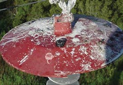
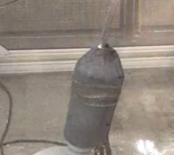
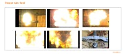
To demonstrate these three essential material properties, this company uses a power-arc testing methodology, as recommended in IEEE 1656. This test simulates the challenging conditions of a power arc in service —generating high voltage, high energy, high temperatures and hot gases in a short period of time.
This is shown in the photos in FIGURES C & D. This test adequately simulates potential ignition scenarios that could actually arise quickly in a power-distribution system, where a high-energy burst from a lightning strike, trapped arc root or fault current is likely to confront the system and individual polymeric components. Such a test is deemed successful if the polymeric insulating component remains intact following the arc exposure and does not deform or catch fire.
In TE Connectivity’s 50 years proven field experience, TE has proven the approach to choose insulating solutions produced with optimized and engineered polymers that have been explicitly derived to reduce or eliminate the fire from starting in the first place, by actively reducing the most common sources of ignition and flame propagation — arcing due to pollution buildup, or flashover of insulation — and not place reliance on self-extinguishing capabilities.
Decades of experience with this company’s broad insulating product portfolio demonstrate that polymers that have been specifically formulated to maximize TERT (tracking resistance), are able to withstand progressive damage from sustained UV exposure, pollution buildup and thermal deformation and this provides better intrinsic protection of utility assets than simply selecting VO polymers that may self-extinguish after ignition has already occurred.
Critical Insulating Components to Protect Overhead Lines and Substations
The opportunity to evaluate the aging infrastructure of an existing power-distribution and transmission system and identify its weaknesses with regard to wildlife-related fire risk, gives operators an opportunity to harden the overall grid improving reliability and reduce the risk of flashover events that can create a fire ignition risk. All new wildlife- or fire-risk-mitigation projects begin with a thorough assessment of the problem at hand.
In its most basic form, this assessment starts with a site visit and interviews with the engineers responsible for the problems being faced. Gathering statistics, photos and site-incident reports is a valuable process that can help to determine the scale, frequency and root cause of outages.
Unfortunately, such detailed information is not always available at the start of the process and cannot be done thoroughly by the utility owner alone. Therefore, a site visit conducted by an insulating specialist, together with the responsible asset maintenance engineer, provides a good starting point. During the visit, this team will:
A. Define the utility operator’s view of the problem, in terms of what types of wildlife routinely interact with that particular system, which elements of the system are particularly at risk, and this is done with a site visit, and review photos of current and legacy issues.
B. Define the highest risk areas the substations, and parts of station that have the shortest phase-to-phase or phase-to-earth distances.
C. Seek evidence of wildlife interactions such as nesting materials, feathers, bones and guano.
D. Gather evidence of flashover, corrosion on the support structures, insulator fittings and broken porcelain.
While conducting a site audit, the implicated equipment is counted and either videoed or photographed. Armed with this data, the wildlife and asset protection specialist will prepare a risk statement, preliminary engineering proposal and quotation related to upgrades needed to reduce potential risk associated with wildlife and vegetation specific to that location.
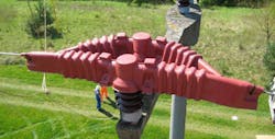
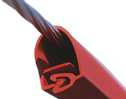
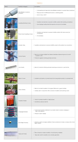
The particular combination of insulating components needed to fortify each site is customized based on the particular challenges and assets encountered at that location. Typically, the overall solution is created using a portfolio of standard and customizable insulating products manufactured from proven Raychem polymeric materials (see Broad Expertise And Experience In Polymer Science). An overview of the most commonly used wildlife and asset protection products can be found in Table 4.
Closing Thoughts
To safeguard their overhead lines and substations from the risk of unplanned outages and wildlife-related fires, utility owners should partner with an experienced vendor and develop a strategic plan to replace, retrofit and/or upgrade the most at-risk assets and enhance insulation throughout the system based on a structured risk assessment process.
Trust should be placed in partners with a proven track record of experience in the field, broad expertise in electrical and mechanical component design and material science. Partners with fully integrated compounding, supply-chain integration, testing and installation demonstrate their dedication to materials science and can help to reduce cycle time and support troubleshooting and quality-control and customer-service initiatives.
The goal is to select and specify insulating and isolating components and enhanced insulation throughout the overhead lines and substations, to mitigate active threats and reduce the risk of outage and associated risk of fire related to wildlife interactions with energized components. Such strategic investment will provide a return on investment by protecting assets and the community from costly and potentially catastrophic wildlife interference — and reduce the risk of flashovers, interference, equipment damage and uncontrolled wildfires down below.
Materials used in such solutions should be designed for 35+ years to match the life expectancy of the expensive assets they protect. The testing specified should be designed to reflect this requirement. Critical to attainment of this 35 year lifetime is proving performance in UV, anti-tracking(TERT), and thermal endurance. TERT test method should be conducted according to ASTM D2303 STEP method incorporating abrasion to reflect the anti-tracking performance of a real-life aged sample.
Broad Expertise And Experience In Polymer Science
The use of strategic engineering upgrades provides an essential solution for a utility operator to fortify their power distribution systems. Selection of wildlife asset protection (WAP) components can reduce the risk of fire and wildfire from interactions with birds and animals, but specification of components with the most appropriate polymer formulation — with an eye toward ensuring the most critical performance attributes — is essential.
A key underpinning of the entire TE Connectivity product portfolio is its use of Raychem polymers, and the deep material science and formulation expertise. In 1962, Raychem International (which was formed in 1957) invented the first heat-shrink polymer for use in the power-generation and distribution industry, and was one of the first companies in the world to commercially deploy radiation techniques and cross-linking to facilitate polymerization and the production of materials and components that could be heated and cooled and shaped, as needed.
Raychem’s innovative material science and polymerization breakthroughs in the 1960s, eventually led to the development of a broad array of wildlife and asset protection solutions in the 1980s whose polymer formulations allow them to withstand fault conditions (such as tracking, flashover and power arcs) that are endemic to overhead power lines and substations. In 1999, Raychem was acquired by TE Connectivity, and the broad technology platform and materials science expertise has continued to grow. Today, TE’s Raychem polymer formulations have been in service for 40-60 years the world over in countless electric utilities, original equipment manufacturer (OEM) systems, industrial applications and more, demonstrating their reliability and longevity.
About the Author
Brian McGowan
Brian McGowan is a senior global portfolio manager, wildlife and asset protection, at TE Connectivity. He has 25 years of experience in the design, development, and deployment of insulation and protection solutions for utilities, rail, and OEM applications. McGowan started his career in R&D and since then has managed several global product groups at TE Connectivity, including the Insulator & Surge Arrester businesses. He currently manages the global Wildlife and Asset Protection (WAP) portfolio, delivering reliability improvement and endangered wildlife protection in all five continents. McGowan holds a BE (University College Galway), MSc Eng(University College Galway) CDipAF (ACCA), MBA (University College Dublin).
Michael Anderson
Michael Anderson is TE Connectivity’s North American business development manager, wildlife and asset protection, Fuquay-Varina, North Carolina, USA. He has been with Raychem/Tyco/TE for 11 years, managing business-to-business relationships in many market segments and working closely to help clients to improve the reliability, resiliency, and safety of their power-delivery systems. He holds a BA from the University of Iowa.
Luis Puigcerver
Luis Puigcerver is TE Connectivity’s product manager for the Americas in the area of wildlife and asset protection, Fuquay-Varina, North Carolina, USA. He has more than 35 years of service at the company, having joined in 1984. Puigcerver began his career in product development in the telecom division of Raychem/TE Connectivity, where he focused on aerial distribution products. For the past 23 years, he has worked in the company’s energy division, both as a development engineer and an application engineer before moving into his latest position in 2008.
