How the Seven-Step Fire Hardening Process Will Reduce Risk for Utilities
Wildfires have been devastating California at a hazardous rate and it has become a serious cause of concern for affected utilities in the area, both large and small. The largest investor-owned utility in the state, Pacific Gas & Electric (PG&E) filed for Chapter 11 bankruptcy this January, claiming it was because of losses from the wildfires of 2018. As the fire season grows longer, the utilities’ matter of ensuring their systems’ reliability in the midst of these incidents becomes increasingly relevant.
However, the long-standing solutions for pole hardening seem dire. Fires can be unpredictable because of their numerous causes, ranging from lack of vegetation management, dry conditions, and the universal constant, humans. People end up creating 84% of wildfires in the United States. A solution that has been considered by many is moving the overhead lines underground. However, as Elizaveta Malashenko, the California Public Utilities Commission (CPUC) Safety and Enforcement division director, points out, that would quickly become more expensive than it was worth, “Underground is about 10 times more expensive than overhead.”
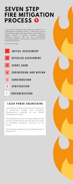
Lazen Power Engineering has developed a solution for a comprehensive hardening effort: a seven-step process that will help mitigate fires and improve overall safety in a utility’s territory. It includes combining traditional hardening practices with the most sophisticated technology available in one process, making it both cost-effective and efficient.
Step One: Initial Assessment
The initial assessment demands two major steps. First, an existing data review and second, drone inspections. The data review consists of analyzing current critical fire zones and historical outage data. With a comprehension of the area’s trends, the system then leads into inspecting the area with an unmanned aerial vehicle (UAV). The UAV is used to capture thermal and high-resolution photos from angles that might not be available from the ground. An additional sensor on the drone can be used to measure the Normalized Difference Vegetation Index, which can identify the health of vegetation. This is critical, as one of the major reasons for outages is fallen trees.
Step Two: Detailed Assessment
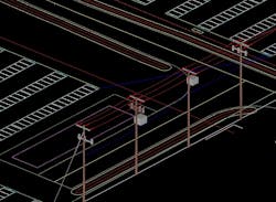
The detailed assessment continues with the use of two tools: light detection and ranging (LiDAR) and a computer aided design (CAD) software for structural and clearance analysis. Collecting land survey is also done using photogrammetry. However, LiDAR is the most accurate way to collect data and the most applicable for power line modeling. LiDAR uses light in the form of a pulsed laser to measure variable distance to the Earth. The data is then collected and put into a 3D CAD software for simulation. Engineers can use the model to create site-specific overhead line design and simulate the effect of wind, ice, maximum operation temperatures on the wires, and other variables that would affect the integrity of the grid. The ideal 3D model should allow for structure analysis, clearance analysis, finite element analysis, and vegetation management. These functions performed in the 3D model are especially important in California, where dry conditions command complete accuracy when designing an overhead distribution line.
Step Three: Score Card
A scorecard is then created to assist linemen, superintendents, and managers in prioritizing aspects of the system. The variables that are on the scorecard are as follows: critical fire zones and outage historical data, visual data, thermal data, health of vegetation, 3D CAD simulation results, equipment addition and/or replacement requirements, and other utility-specific variables to be considered.
Step Four: Engineering and Design
Designs are created in the 3D modelling software to resolve the found code violations for compliance with National Electric Safety Code (NESC) and California’s General Order 95 (G.O. 95). The ideal CAD software should allow the user to create custom design criteria, even inputting hardware data directly from the manufacturer. Such data can be used in the 3D model and simulation in order to ensure all poles, wires, and components are structurally sound.
Step Five: Construction
The 3D model can be used to generate all components of a construction package. Some of those components are plan and profile drawings, SAG tension reports, stringing charts, construction staking tables, and more. The number of components needed depends on the construction work required. FAA reports, hardware engineering calculations, Google Earth KMZ files, a structure usage report, individual pole reports, and other overhead and underground construction documents are all examples of more variables that can be used to head new construction and rebuilds. When construction uses such detailed documents, power lines can be built according to precise design using sophisticated tools and can truly improve grid resilience.
Step Six: Verification
After structures are built and new wires are strung, it is now time to ensure that they have been built correctly. Collecting as built LiDAR (remote scanning again after construction) can ensure that the poles align with design specifications. This verification process allows comparison of what was built against what was designed, ensuring the correct hardware was installed as listed in the construction documents and double-checking in the 3D model for code compliance. If any violations are found, this is the time to act and issue a modification package to correct said violation.
Step Seven: Documentation
The final and most important step of the process is to ensure proper documentation, proof of compliance, and ideal record keeping. The 3D model can be used for all of the above, as it would document:
- the “nature of the work” under G.O. 95 Section 1 Rule 18
- the “records of these calculations for the service life of the pole or other structure for which the loading calculation was made” under G.O. 95 Section IV rule 44.1
- the “loading calculations for the service life of the pole or other structure for which a loading calculation was made” under G.O. 95 Section IV rule 44.2.
Drone inspections also contribute toward the requirements of annual/biannual “patrol inspections” in compliance with G.O. 165. A report that complies with California’s G.O. 95 design documentation requirements can then be used to provide support for legal disputes and in public meetings.
Lazen Power Engineering has worked with several California utilities and industry partners in regard to their fire mitigation needs. Mohammed Issa, the company’s founder said, “Our team’s dedication and daily hard work by performing these 3D models and simulations is contributing toward the resilience of the grid, one pole at a time. At the end of the day, if one pole at one location will save one life, we will be happy.” As a whole, Lazen Power Engineering has performed hundreds of 3D models of overhead transmission and distribution lines, working with industry partners on fire hardening efforts. The company maintains attention to detail and an appreciation for the client’s exact needs, which is part of why they created this seven-step fire hardening process.
“We are facing unprecedented conditions in California,” CPUC’s Malashenko said. “We are facing a crisis at the state that has not been faced before.” The state legislature has passed a new law, the SB901. From the beginning of this year, utilities are required to have vegetation management, electrical inspections, and power systems that would allow them to take outages when the fire danger was high. Not only that, but penalty maximums are now doubled when a utility is discovered to be in noncompliance with safety regulations. There is now a serious legal risk to the predicament that is fire risk mitigation.
3D modeling and simulation of overhead line conditions is the only true way to provide certainty of preventing incidents because of noncompliance or structural and clearance issues. For many years, overhead transmission line construction has been implementing such engineering and design practices, playing a major role in improving the lines’ grid resilience. However, overhead distribution lines currently rely on basic design tools, old standards, or neither. With challenges from the environment facing the power grid these days — fires, hurricanes, blizzards, and so forth — it is time that maybe the industry should shift toward applying the most sophisticated tools and software available to engineers and designers to prevent occurrences before they happen.
With everything considered, a thorough fire-hardening process may be the answer that these utilities have been looking for. Whichever decision is made must be reached soon, because unfortunately for utilities, it’s August. The California climate is not going to wait until a consensus is reached.
Sidebar: Seven Step Fire Mitigation Process
About the Author
Mohammed Issa
Mohammed Issa, P.E., is acting as director of Engineering Transmission and Distribution at Lazen Power Engineering in Orlando, Florida. Issa has 11 years of transmission line industry experience involving civil and structural engineering from 12 kV to 500 kV and a broad experience including utility, engineering-procurement-construction (EPC) contracts, and as an engineering consultant. Issa has also designed and successfully led a variety of transmission line utility projects from start to close, in compliance with codes and client standards.
Danielle Adoghe
Business Development Lead
Danielle Adoghe, business development lead at Lazen Power Engineering, is a business professional in the power delivery industry, with years of technical writing experience. Adoghe has helped local startups with their strategic planning and project management. She is adept at fostering relationships and creating partnerships between utilities, engineering firms, and other industry partners.


