Low-Voltage Bushing Box and Low-Voltage Bushing Leaks Root Cause Analysis
Bushings are the most critical component of a low-voltage (LV) transformer. They are important to the transformer’s operation because they are active parts. Unfortunately, bushing failures are the major causes of transformer failures. These leads can lead to costly consequences: oil spills, explosions, fires and the significant cost to replacing the bushing, but the resulting transformer failure can also incur additional costs, and more importantly, the downtime and outages. Aged oil seals, which lead to oil seal cracks are predictable causes of transformer leaks, but other culprits include adverse cold and hot weather condition, which cause premature rusting of bushing pockets and undesirable leaks.
At first glance, a leak on an oil-filled transformer seems only to be an annoyance. But oil leaks from a transformer tank range from an unsightly nuance to a huge environmental event. If a leak goes undetected or low-level alarms fail to operate, then there is a high risk of an internal flash over and a transformer failure.
The two root-cause investigations covered here yielded the solutions to prevent reoccurrence. The first leak addressed is oil leaking from the main tank. This leak was detected on a simple inspection round. Routine maintenance temporarily fixed the issue. But the issue came back because the root cause was not identified. The second leak was hidden until another event called for an investigation that led to the discovery of the leak on the transformer.
Problem Statement (Object + Defect + Consequences)
Object (1) – Low Voltage (LV) Bushing Box gasket / Object (2) – Low Voltage (LV) Bushing gasket
Defect (1) – Leaking externally / Defect (2) – Unseen Leak into the Bus Duct
Consequences (1) – A point of moisture ingress which will attack and weaken the paper insulation of the transformer thus shortening the life of the transformer / Consequences (2) – Risk of flash over in the LV bus that could potentially fail or damage the transformer and/or the generator
Background
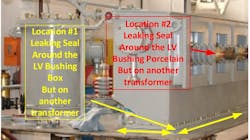
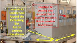
Two different leak locations were reported by maintenance personnel. The first leak was the low-voltage bushing box gasket. This gasket seal is located between the top of the transformer and the bottom of the bushing box. However, this gasket seal is below the conservator tank, which holds a nominal 252 gallons of oil. The failure of this gasket seal is a slow leak, and this is not a failure mode that would allow for the rapid release of oil that would cause an environmental event or an immediate catastrophic failure of the transformer, before being seen on a normal weekly or monthly visual inspection round.
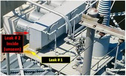
The second leak was reported to be associated with the LV bushing. The bushing is mounted horizontally. See Figure 1. The air side is located inside the LV bus duct while the other side is located in the same oil containment as the transformer. The bushing itself is solid porcelain with a center conductor. See Figure 6. The bushing has seals between the center conductor and the porcelain insulator, which prevents transformer oil from leaking out. Another seal is between the bushing box and the bushing mounting flange If either seal is compromised, transformer oil would leak into the bus duct and go unnoticed on normal inspection rounds. The conservator is located above the LV bushings, and if a leak was to develop then a large amount of oil could leak out before being discovered. Dust and debris would collect on the oil film and over time would cause a conductive path to develop to the point of a flashover.
Investigation – Leak #1
While talking to maintenance personnel onsite, it was said that once the leaks were discovered, the bolts around the LV bushing box were tightened and the top of the transformer cleaned. Before performing any work, the seal between the bushing box and the top of the transformer was inspected. No leaks were found.
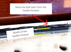
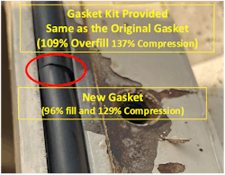
The LV bushing box on was unbolted and raised up for inspection and re-gasketing. It was reported that the bolts on the front of the transformer was tight and the bolts under the LV bus duct (hard to reach area) were NOT tight. Upon inspection, the gasket was found to be made of the proper oil resistant material, but the gasket groove was found to be overfilled. See Figure 3. Overfilling of any gasket groove leads to the two mating surfaces not able to properly mate, thus causing a leak over time as the gaskets age. Tightening can temporarily help but does not resolve the issue long term.

Corrective Action for Leak #1
To prevent the reoccurrence of this type of leak, the following actions took place. The groove was inspected, cleaned, and a new properly sized gasket installed using an oil compatible (Nitrile Butyl N) O-ring. In addition to the installation of a new and properly sized gasket, it is recommended to check and tighten all nuts associated with any new gaskets at the first testing cycle which is typically three to five years. The OEM states on new transformers to check and tighten nuts after one year. But this is often not practical due to the operational constraints of most transformers.

Investigation – Leak #2
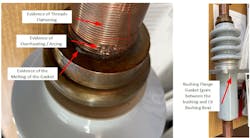
While inquiring about the second leak location, it was told that a LV bushing was found leaking into the bus duct. Then it was discovered that air side LV terminal was found to have over heated. See Figure 6. The overheated connection got so hot that the threads and gaskets were damaged. The bushing was replaced.
Corrective Action for Leak #2
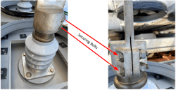
Any LV bushing showing signs of having a leak or thread damage due to an overheating event must be replaced because the internal gasket will be compromised. The LV bushing flange gasket is external to the bushing itself and goes between the bottom of the bushing flange and the LV bushing box. This gasket should also be replaced when installing a new bushing. For the electrical connection, the LV bushing terminal is screwed onto the top of the bushing, then the securing bolts must be tightened. See Figure 8. The connection between the bushing conductor and the bushing cap is then verified by a micro-ohm test. The micro-ohm for this connection must be 20 micro-ohms or less. See Figure 7. Another less sensitive method for finding a gross loose bushing terminal connection is to question a LV winding resistance reading greater than 5% over the factory resistance.

Extent of Condition for Both Types of Leaks
In both cases, once the root causes were fixed, we took proactive steps to ensure they never happen again.
The Extent of Condition for Leak type #2 exist on bushings that does not have documented micro-ohm readings in a test report or maintenance records.
The Extent of Condition for Leak type #1 exist on a gasket grove that has been over filled and not rechecking the tightness of all nuts at least by the first routine testing cycle.
Mark B. Goff, MS EE PE ([email protected]) is a member of the T&D World Executive Insights Board and is responsible for multiple technical publications. Goff's experience spans a 34-year career at Tennessee Valley Authority (TVA). from field test engineer, systems engineer through to manager of the electrical energy conversion group in generation engineering, Goff built an effective transformer, breaker and infrared test program and maintenance support group. He currently is an engineering consultant for TVA’s Power Service Shop.
Cassandra H. Goff, MS EE PE presently works for Qualus as a relay protection engineer. Prior to joining Qualus, she was manager of the electrical balance of plant, generation engineering at TVA. For 10 of her 26-year TVA career, she was a relay protection engineer. She also has more than 14 years of experience working as a system engineer for the TVA transmission organization, working to develop an effective relay maintenance program and building talent to support the program. Also, she was an adjunct professor in the electrical engineering graduate program for the University of Tennessee at Chattanooga.
Collin Jay Rosson currently works for TVA at the Power Service Shops serving as a Production Engineer in the Transformer Services group. Jay has previously worked in the electrical design/construction field. Primary experience includes designing and implementing internal power distribution systems for chemical plants and pulp and paper mills. Jay is a registered Engineer in Training (EIT) and currently pursuing his Professional Engineering (PE) license.
About the Author
Cassandra H. Goff
Cassandra H. Goff is an adjunct professor in the electrical engineering graduate program for the University of Tennessee at Chattanooga and works for Patterson Power Engineers (PPE). Prior to joining the PPE, she was manager of the Electrical Balance of Plant, Generation Engineering, at Tennessee Valley Authority (TVA). For 10 years of her 26-year TVA career, she was a relay protection engineer. She also had over 14 years of experience working as a system engineer for the TVA transmission organization as a system engineer, working to build an effective relay maintenance program as well as building talent to support the program.
Mark B. Goff
Mark B. Goff is a member of the T&D World Executive Insights Board and is responsible for multiple technical publications. His experience spans a 34-year career at the Tennessee Valley Authority (TVA) — from field test engineer to systems engineer to manager of the Electrical Energy Conversion group in Generation Engineering. He built an effective transformer, breaker, and infrared test program and maintenance support group. He is currently working as an engineering consultant.