Testing of Key Offshore Transmission System Components
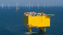
Offshore is the new frontier in the search for renewable energy. The potential expansion target for North Sea in Europe is 300 GW by 2050. According to the European Commission, an estimated 240 GW to 450 GW of offshore wind power in Europe's seas and along its coasts will be needed by 2050 to keep temperature increase below 1.5°. The special conditions that exist (harsh weather, long distance) pose numerous and unprecedented challenges to the components that shape the new transmission grids. The difficult servicing conditions require reliability and availability of the components.

In this article, we highlight three special test projects ran by KEMA Labs, the TIC CESI Division, together with the manufacturing industry and offshore system operators, regarding the verification of cables, switchgear, and transformers dedicated to offshore operation. For this special application, new stresses were evaluated and new test methods and circuits were developed and demonstrated.
KEMA Labs is a world leader in the testing, inspection, and certification of electric power equipment. Its six specialized laboratories in North America and Europe have ample experience operating on the frontiers of innovation in today's energy transition, centralized around decarbonization, decentralization, and digitalization.
Tennet is a leading cross-border European electricity transmission system operator (TSO) with its main activities in the Netherlands and Germany.
HVDC cables
Power cables are energy highways to land-based stations. Submarine cables are prone to failure: HVAC submarine cables suffer 1 to 3 faults per 1000 km per year, whereas HVDC submarine cables fail a factor of 10 less frequently. Repair can take months and 70% to 80% of payouts from insurers to windfarm operators are cable fault-related. Testing and certification is a major aid in outage reduction.
Testing of HVDC cables has two additional requirements that are absent in ac:
- A specified temperature drop is required across the solid cable insulation. In dc, the electrical field distribution in the insulating material is determined by conductivity, which is temperature dependent. At high load, the highest electrical stress is near the sheath, whereas in no load it is near the conductor. High-voltage testing always needs to take place under actual (cyclic) load conditions.
- Composite voltage tests are required, implying that positive and negative switching and lightning impulse voltages are superimposed on the dc system voltage level.
Standards have been developed, such as IEC 62895, that describe testing procedures for HVDC XLPE land cables. CIGRE provides additional recommendations for testing both land and submarine cables. These procedures must be applied to qualify a cable for operation in HVDC grids, though these requirements must be considered as minimum. Grid operators define additional quality requirements that are not covered by the standards. Temporary overvoltages (TOV) may occur during the operation of the cable in a grid. From system studies by TenneT, two categories of TOV were identified in case of failure:
- Category 1: Slow impulse type dynamic voltages. This represents a TOV profile that resembles a double exponential type impulse with slow wave front (around 10 ms) and tail time matching the service configuration in the range of 100 to 200 ms. This characterizes the non-faulty pole in an event of a failure on the other pole.
- Category 2: Zero-crossing damped oscillatory discharge voltages. This mainly characterizes the faulty pole that experiences a capacitive discharge with an oscillatory profile. This category comprises high-frequency oscillatory voltages (frequency above 5 kHz) and low-frequency oscillations (below 400 Hz).
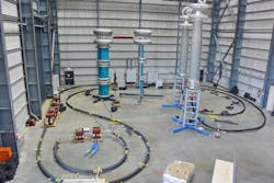
A special test is designed by KEMA labs and TenneT to cover both categories of TOV and demonstrate the performance of HVDC cable system rated up to 525-kV dc with the existing HV test facility of KEMA Labs in Mannheim, Germany.
In this facility, HVDC cables up to 525 kV are type tested or submitted to long-duration pre-qualification tests.
HVDC switchgear
HVDC switchgears are key equipment in the control of power and protection against faults in large offshore HVDC systems. KEMA Labs demonstrated the testing of two types of new switchgear for offshore: HVDC circuit breakers and HVDC gas-insulated switchgear (GIS). All demonstrations were conducted within the framework of the European PROMOTioN project on offshore transmission grids, which was completed in 2020. The challenge for KEMA Labs was to validate components of future HVDC grids. KEMA Labs, as a project founding father, was a partner of choice because of its reputation in innovative test technologies.
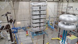
Three HVDC circuit breaker technologies, rated 80 to 350 kV, were tested in a high-power laboratory, and one long-duration (more than a year) high-voltage withstand test of an HVDC GIS (320 kV) was performed in a high-voltage laboratory of KEMA Lab's site in Arnhem, the Netherlands.
At first, system studies led to an understanding of the impact of transients on switchgear in a faulted grid. A key duty for HVDC circuit breakers is massive energy absorption. By operating ac short-circuit generators in low frequency, for the first time ever, tests could be performed covering the complete interrupting cycle of a fault current up to 20 kA in a meshed HVDC grid. For the largest circuit breakers, six short-circuit generators were needed. This means that, unlike earlier tests elsewhere, all breaking functionalities can now be tested in a single "shot" as in service, leaving no doubt to the end-user.
Industrial partners supplied the three different technologies of circuit breakers: Mitsubishi Electric (Japan) provided an active current injection HVDC circuit breaker based on high-voltage vacuum circuit breakers. Hitachi ABB Power Grids (Sweden, Switzerland) provided a hybrid HVDC circuit breaker based on semiconductors as well as a HVDC GIS. SciBreak (Sweden) brought in a new type of converter-assisted vacuum arc-based dc circuit breaker.
Power transformers
Transformers need to adapt the voltage to suitable levels. Most relevant are the power transformers that in ac transform the voltage to transmission levels and in dc supply the power to converters. These components are difficult to service and replace. Offshore accessibility, especially, is a major issue.
Failure data from CIGRE show a major failure rate of 0.5% (for converter transformers this number is between 2% to 5%). Because of the very large electrodynamic forces that impact the compact winding structure, passage of short-circuit current is an extreme stress for transformers. These internal forces are in proportion with the square of current and the inverse of conductor distance. From EPRI Transformer Industry-Wide Database (IDB), inadequate short-circuit strength is by far the main reason of transformer failure. Moreover, KEMA Labs has conducted almost 400 short-circuit withstand tests on power transformers with power ratings between 25 to 600 MVA, up to 800 kV, in the past 25 years, confirming that around 25% does not pass the short-circuit test as specified in IEC 60076-5. The dominant failure mode is not only mechanical deformation of the winding but also oil spill and damage of bushing. In land-based stations, such failures are disastrous, but loss of a transformer on a platform has even greater impact on system availability. It is CIGRE's position that short-circuit testing is the most comprehensive solution because all parts are verified.
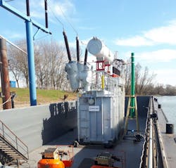
This is especially the case for transformers with special winding arrangements. One such design is an axially split winding transformer having two secondary windings. In case of a short-circuit current flowing through (only) one of these, the clamping construction must contain the highly unbalanced forces in the transformer. Recently, KEMA Labs tested such a design of a 220-kV/400-MVA transformer with two secondary windings intended for offshore installation. In the test, short-circuit current was generated in one secondary winding while the other was open. This transformer, designed by Royal SMIT (Netherlands), passed the short-circuit test because the impedance change remained below 1% as required in the standard and no external abnormalities were observed.
Conclusion and outlook
Offshore application of T&D equipment is becoming a fast-growing market. Compactness of offshore equipment is a major requirement, minimizing insulation distances and reducing maintenance extremely because platform space is in the order of 100 k€/m2 while maintenance costs exceed far the onshore practice. Equipment for floating platform and even seabed stations will be applied in the future.
Control (mostly remote) of power in HVDC transmission schemes will be more complex than before, especially when meshed grid topologies emerge. As an example, FlexPowerGrid laboratory experimented with methods for testing control of multi-module converters (MMC) using hardware-in-the-loop, including converter harmonic impedance measurement and dynamic performance assessment. This project was in cooperation with NR Electric (China).
Switchgear up to 66 kV, even SF6 gas-free, is common nowadays to be installed directly in wind turbines. Compact GIS is installed on platforms and application of offshore HVDC GIS will soon be realized. Special circuit breakers are needed to act in case generating units need to be decoupled or synchronized. In case of ac-connected offshore windfarms, often very long cables are used. This means switching of high capacitive currents well above the standardized values. In addition, compensating reactors are installed onshore, which can lead to situations of ‘missing current zero,’ unheard of in onshore cable switching applications.
The new offshore testing and equipment technology comes with various innovative aspects: massive power electronics, SF6 alternative gases for offshore, ultra-fast drive technologies, AI-based protection, high-voltage dc sources up to 3 MV, simulation, remote testing, and witnessing under severe COVID-19 restrictions, optical, ultra-high bandwidth measurement, and more innovative signatures of the future energy equipment testing technology.
About the Author
René Peter Paul Smeets
Service Area Leader
René Peter Paul Smeets is innovation specialist at KEMA Labs. He received a PhD for research work on switchgear in 1987. Until 1995, he was an assistant professor at Eindhoven University, Netherlands. During 1991, he worked with Toshiba Corp. in Japan. In 1995, he joined KEMA, the Netherlands. In 2001, he was appointed part-time professor at Eindhoven University, the Netherlands. In 2013, he became adjunct professor at Xi’an Jiaotong University, China. Dr. Smeets has leading positions in CIGRE, IEC, and is a fellow of IEEE and chairman of the Current Zero Club, a scientific study committee on current interruption. He published and edited three books and authored more than 300 international papers on testing and switching in power systems. He received eight international awards.
Nadew Adisu Belda
Nadew Adisu Belda is innovation engineer at KEMA Labs, responsible for the development of test methods and design of test circuits for HVDC switchgear. He is currently finalizing a PhD at Technische Universität Darmstadt (where he studied as an external candidate), Darmstadt, Germany. Belda is a member of IEEE, IEC, and CIGRE, and actively participates in related international working groups. In 2019, he received the Wang Jimei Young Investigator award for his contribution at an international conference.
René Bruil
René Bruil is head of Global Scheduling HPL. He is currently responsible for the planning of the High Power Laboratories and for transformer testing activities. He has more than 25 years of experience in the field of short-circuit testing of MV and HV equipment, eight years as a test engineer, five years in the certification department, and the last years as a planner of the High Power Laboratory and transformer business. He was a member of the IEC working group MT45 for switches and is currently a member of the STL Technical Committee.
Tanumay Karmokar
Tanumay Karmokar is a specialist engineer at TenneT TSO GmbH in Germany. He is currently one of the lead responsible asset engineers for designing and specifying technical requirements of HVDC cable systems for offshore and onshore interconnector projects in Germany up to 525-kV level. He has 10 years of industry experience in various domains, which include onsite testing and commissioning, designing high-voltage test circuits for cables and transformers, and development of HVDC cable systems. He has a master's degree from the Brandenburg University of Technology in Cottbus, Germany, with a focus on High Voltage Systems Engineering. Karmokar is a member of CIGRE.
Heiko Jahn
Heiko Jahn is principal engineer and special projects at KEMA Labs FGH Engineering & Test GmbH, Mannheim (Germany). Since mid-2020, Jahn works as project coordinator for Central Europe. He has worked since 2006 at FGH Engineering & Test GmbH, initially as head of High-Voltage Test Laboratory and then as head of High-Voltage and High Power Test Laboratory, platform manager of Mannheim Platform and principal engineer and special projects. Jahn has been a member of CIGRÉ WG A3.18 from 2003 to 2006. He previously worked at Siemens AG and has a doctor degree in engineering, Dresden Technical University, Germany.