Getting Offshore Wind Power on the Grid
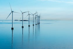
Wind power in North America has been an exclusively land-based resource until December 2016 when the 30-MW five turbines Block Island Wind Farm began supplying power to the grid from off the coast of Rhode Island. Offshore wind power plants now look to be competitive, and several projects are in the planning phases. The emergence of larger wind turbines with designs that eliminate maintenance-intensive gearboxes, coupled with the use of offshore petroleum expertise, have reduced costs and allowed projects to be economically feasible.
Wind power projects overcome what are often large electrical distances, to bridge the gap between the locations of the best wind resources that are often remote from population centers needing the power. An amazing aspect of the North American wind industry has been its ability to secure right of ways and build transmission tie lines, some transmission lines traversing 50 miles or more. The offshore wind industry will also be meeting the challenges of landing the power onshore and transporting it to where it is needed.
The bulk electric transmission system typically ends at the shoreline, where the system loads come to an end. An offshore wind plant will typically be located nearest a transmission substation and that will present some challenges. Redirecting power flows from “the end of the system” will mean challenges that will need to be understood and overcome with system reinforcements.
Collecting the Power from Turbines
Wind power plants utilize medium voltage (most commonly 34.5 kV) collection systems that consist of underground cables. Typical projects have to traverse 50 miles or more to collect power from all the wind turbines. The collection system substation also includes reactive power control components such as capacitor banks, but offshore projects are likely to provide this support at the interconnection onshore.
The main issues at the collection substation include controlling the reactive power, maintaining acceptable voltage levels, and ensuring that the power quality allows the wind turbines to operate reliably. Offshore wind plants will want to avoid putting harmonic filters on marine platforms. So it can be expected that these turbines will provide active harmonic damping in their power electronic controls, negating the need for offshore harmonic filters.
Landing the Power Onshore
The emergence of deeper water techniques is allowing the industry to locate projects further from the shore, minimizing some environmental concerns. Getting power onshore requires high voltage. For high voltage ac (HVAC) transmission, generally the HVAC marine cable plays a major role in limiting the technical and economical feasible length between the onshore substation and offshore wind farm. Offshore wind developers are considering high voltage dc (HVDC) when the charging current and losses of an ac cable are too high.
The main equipments of a dc system are the power converters. They are the key components to make an economical comparison between ac and dc transmission systems. Dc cables themselves are less expensive than ac cables, because for a given amount of insulation they can be operated safely at a higher current, allowing more power per cable. However, the overhead costs of the power converters at either end of the transmission line are considerable. Other issues with dc include system complexity, such as maintenance requirements of a converter station at sea. There can also be some control interactions between the HVDC system, the wind power plant controls, and the wind turbine controls that could be problematic.
While there are technical issues and concerns with ac transmission, these considerations can be evaluated and overcome. For ac transmission, switching off the ac cables can result in excessive transient, temporary and sustained overvoltage conditions on the power system. Switching surges can also be significant with long cable systems. Energizing and de-energizing switching operations can result in significant transient overvoltages and overcurrents on the power system.
A potential condition that may lead to high sustained overvoltages is the energizing of a long ac cable from a predominantly weak source. Sustained overvoltages may also occur due to a sudden loss of load. High steady state overvoltages can be caused by unbalances in the system voltages during single line-to-ground faults. Uncontrolled cable energizing can result in similar transient overvoltages as that from capacitor energizing. Switching studies can develop a set of operating procedures that fall within maximum sustained voltage ratings of connected equipment, insulation levels, surge arrester characteristics, and the probability of a given overvoltage occurring.
In case of a cable, however, the transient overvoltages at the receiving end of an open cable can be higher due to the Ferranti effect, and the doubling of the transient reflection at the open termination. The sustained voltage following cable energizing is a result of the voltage rise caused by the capacitive charging current flowing through the source and transformer reactance. The sustained voltage will be a function primarily of the source impedance, the cable length, and transformer characteristics. These overvoltage effects can be dealt with by compensating the voltage rise effects with shunt reactors. But these reactors also require some studies. Is it possible to energize the main transformer, cable and reactors together as a unit? What are the operational problems? One important issue, called the zero-missing phenomenon, arises with energizing cables and shunt reactors together, that occurs during a fault and has to be accounted for.
The zero-missing phenomenon is defined as an ac current not crossing zero value during several cycles. Generally, the energization of the cable capacitance results in a high-frequency ac component superimposed on the power frequency (50 Hz or 60 Hz) charging current. Energization of the shunt reactors results in its ac current component, plus a dc component. At 100% compensation, the cable charging and the shunt reactor ac currents cancel, leaving the dc component and the high frequency capacitive switching current. The dc current persists a long time (seconds) because its decay-time constant is established by the relatively large inductance and the small resistance of the shunt reactors. If the circuit breaker was commanded to open during this time, it would draw an arc but would not immediately interrupt because of the absence of a natural current zero crossing. This could expose the circuit breaker to duty outside of standard capabilities.
Figure 1 shows the results of a zero-missing study, showing the delayed circuit breaker current zero crossings caused by the full shunt reactor compensation at an offshore wind plant. Switching studies identify these problems, and find solutions in terms of energizing sequences that avoid these concerns.
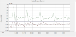
Figure 1: Delayed Circuit Breaker Current Zero Crossings with Full Shunt Compensation
Onshore Considerations at the Point of Interconnection
At an onshore substation, the wind plant will form a point of interconnection with the existing transmission system. The nearest transmission substation to a wind plant onshore landing point may have a relatively low short circuit ratio (available fault levels versus wind plant size) where the plant reactive power swings can greatly influence the substation voltage levels. The substation may also have (or be located near to) a static var compensation or STATCOM to control the voltage at the edge of the transmission system. In these cases, control interactions are possible between the wind plant and the transmission system components. In such cases, EMT models can be used to evaluate various droop control slopes, deadbands, and delay settings. Coordination can be evaluated so that the wind plant controls do not fight against other transmission system components working to control the system voltage.
The connection of relatively long ac cables introduces significant capacitance at the point of interconnection. These cables form lower order harmonic resonances with the system, which magnify the existing harmonic distortion levels on the system. C-filters are a specific type of harmonic filter that includes resistive damping, and are a good choice for onshore substations. The filters can control harmonic resonances and avoid the magnification of background harmonic voltage levels.
Electrical Transmission Considerations
The effect of an offshore wind plant upon the rest of the system will require studies of power flow considerations, given that there is a new power source. Contingency analysis will be done to look at the transience stability of the transmission system if the wind plant was to trip. The redirection of power flow will affect thermal ratings of individual power lines, and voltage considerations. The study may be done in a “queue” fashion, where the sequence of other projects can greatly affect the results and findings.
Power purchase agreements may require the wheeling of power from the onshore point of connection through another entity’s system. The availability of “firm” transmission corridors would need to be confirmed by studies. A big concern is congestion, where thermal (or stability) constraints may require a plant to curtail its output. Congestion may or may not significantly impact the economics of a project. A constraint that introduces curtailment for only a few hours in a year may not be much of a concern. But a constraint that spans hundreds of hours could be a “show stopper.” A good understanding of these constraints or possible curtailments can only be gained by performing production simulation studies, that encompass an 8760 analysis.
Conclusion
There are a number of challenges that offshore wind power plants will meet to achieve the transportation of renewable energy from the turbines in the ocean to the load in which it may serve. Different power flow conditions may increase or improve transmission system congestion, and an annual profile production simulation may be fundamentally important to understand the project economics with respect to constraints or curtailments.
At the landing substation, control interactions and harmonics concerns will be met by careful plant studies and design. Harmonic filters may be necessary at the point of interconnection to manage the resonance considerations introduced by the extensive high voltage cable system. Reactive power droop controls with carefully chosen deadband and delay control characteristics will mitigate the possibility of control interactions.
HVAC power cables are possible for connections of 50 miles or more, but these will require cable midpoint compensating reactors. Extra breakers and switching schemes will be necessary to avoid the zero-missing phenomena that can happen during faults on energization. However, this equipment will provide a lower cost of ownership than dc-based systems.
Offshore wind plants will use larger turbines with designs eliminating a gear box. Construction and maintenance techniques will be adopted from the offshore petroleum exploration industry. Active harmonic filters will be integrated into the wind turbines to manage harmonic concerns on the collection system, avoiding the need for offshore harmonic filters.
About the Author
David Mueller
David Mueller, P.E., is the director of Energy Systems Studies at EnerNex, currently leading the teams producing solutions for projects related to variable generation modeling and interconnection, oriented around transmission and distribution systems, as well as electrical interactions between wind and solar plants, and the electric power system. Mueller has worked for over 20 years on a wide variety of power quality issues, producing solutions for industrial, commercial, and utility clients.