How PG&E Replaced a 230 kV Tower in an Active Landslide Zone
Key Highlights
- LiDAR surveys and field monitoring tracked landslide movement and identified a tower at risk of failure.
- Engineers replaced an adjacent structure with a taller tower and rerouted the span around the unstable slope.
- Hourly survey measurements, geological oversight, traffic controls and engineered access helped protect crews and the public.
- Helicopters delivered materials and erected the new tower, enabling the threatened structure to be removed before further rainfall.
- Early ordering of long-lead materials and field verification of wire tension were key lessons from the emergency project.
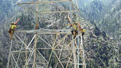
Two years ago in California, a hydro patrol team discovered ground movement and slope instability near a 230 kV tower just 0.3 miles from the Pacific Gas & Electric (PG&E) Belden Powerhouse. They quickly escalated the concern to the PG&E’s transmission line engineering team, who collaborated with the Geoscience Department to deploy a thorough site reconnaissance under immediate-response protocol.
After conducting the field assessment, they learned the landslide was far larger than initially anticipated. The initial estimate placed the landslide area at more than 520 ft by 370 ft, with a deep-seated slide greater than 10 ft deep.
PG&E then ordered a LiDAR survey to further define the landslide and assess its potential impact. With the new LiDAR data, the Geoscience team accurately mapped the landslide limits using elevation differencing, a process that identifies changes in ground-surface elevation between two survey periods.
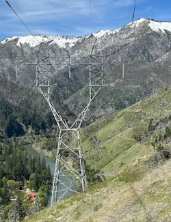
The analysis determined that one lattice tower was located within the landslide zone. The engineering team also overlaid LiDAR data from October 20, 2019, with the new LiDAR data obtained on October 19, 2024, and identified a 2-ft lateral shift in tower 15/115 during that time frame.
In addition to the LiDAR survey, field crews noted cracking along the roadway leading up to the powerhouse. To minimize the effects of the landslide until an engineering solution could be implemented, PG&E used temporary mitigation efforts and continuous monitoring. Meanwhile, workers covered the cracks with Visqueen plastic to prevent water intrusion during heavy rainstorms and significantly reduced traffic on the access road.
Devising a Plan
The engineering team discovered that Tower 15/115, the tangent structure in the landslide area, needed to be removed to avoid a catastrophic failure as the landslide progressed. Removal of this structure, however, would have created ground clearance violations under maximum electrical loading conditions. To make matters worse, this area is in a high-fire-threat district (HFTD).
Engineers acted urgently to uphold their call to maintain the safety and well-being of the public. Working as a team, the engineers determined the best course of action was to replace the adjacent dead-end (DE) structure 15/114 with a taller structure, remove tangent structure 15/115 and span from new DE 15/114 to existing DE 15/116.
Burns & McDonnell was initially retained to lead the engineering design of the replacement structure. After determining the appropriate height and leg extensions for the replacement tower, the team ordered all long lead material. Any delay in ordering and delivering materials would have risked the landslide progressing before the tower could be removed.
Surveying the Structure
As the team was working on the design, continuous monitoring identified additional shifts in the landslide. By February 2025, heavy rainfall in the area had caused the landslide to further progress. The access road to the powerhouse became inaccessible without significant road and drainage improvements, and cracks continued to develop.
The engineering team ordered an additional LiDAR survey on April 3, 2025. The data showed the structure had shifted laterally another 2 ft, bringing the total to 4 ft from its original location in October 2019. Longitudinally, the team noticed a 1 ft deflection at the top of the tower.
The tower began leaning, and redundant tower members became significantly overstressed, as evidenced by field observations of buckled members in compression. Additionally, the team noticed an overstress under everyday conditions for the 3/8-in. steel shield wire during PLS-CADD modeling.
Fortunately, the field measurement of the tension was lower than the model predicted. Deflection in the tower made precise modeling difficult. However, the team added hardware to the shield-wire DE attachment to reduce the tension to within the allowable limits. Additional geological data confirmed the initial landslide area was accurate. The survey data also showed significant elevation changes.
One of the project’s greatest challenges was ensuring crews could safely work within an active landslide zone. While geotechnical investigations indicated the slope was stable enough for construction, the consequences of unexpected movement could be severe. As a result, the project team implemented extensive monitoring and safety protocols designed to protect both workers and the public.
Key safety measures included:
- Traffic Control. Closure of one traffic lane below the landslide area, one-way traffic operations managed by flaggers and reduced public exposure in the event of slope movement.
- Continuous Survey Monitoring. Prism targets installed on tower legs, survey crews conducted hourly total station measurements and real-time monitoring provided early warning of tower or ground movement.
- Full-Time Geological Oversight. A geologist was required on site whenever crews were working within the landslide zone. Existing ground cracks and tension fissures were routinely measured and documented. Continuous observation helped identify signs of accelerating movement or crack propagation before conditions became unsafe.
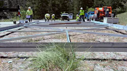
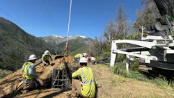
- Engineered Worker Access. Tower climbing within the landslide zone was prohibited. Landslide-affected soils adjacent to the tower were over-excavated and keyed into competent native ground. A temporary level work pad was constructed to support a man lift and provide safe access for conductor-transfer activities.
These layered safeguards enabled construction to proceed while maintaining a high level of situational awareness. In a landscape shaped by movement, success depended not only on engineering solutions, but also on constant monitoring, disciplined safety practices and a commitment to ensuring that everyone returned home safely at the end of each day.
Making the Project a Priority
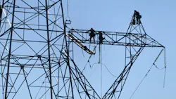
The team elevated the project to an emergency installation and completed the design efficiently. The team replaced the existing 66-ft-tall structure 15/114 with a new 135-ft-tall tower to meet ground clearance requirements.
Spotting the new structure proved to be both challenging and critical. Given the challenging terrain, it was imperative to spot the structure as close to the road as possible. However, because of the nearby hydro facility, the road was also part of the FERC boundary, and the structure needed to be positioned at least 10 ft from it.
In addition to the limitations on structure placement, access to the roadway was also challenging due to deteriorating conditions. The final location of the structure was 27 ft offset from the existing alignment, balancing ROW requirements, FERC boundary requirements, access constraints, structural limitations and ground clearance requirements. The final span length from 15/114 to 15/116 was 1,756 ft.
Due to the project’s emergency nature, the FERC permitting process was expedited. The environmental and permitting teams worked quickly and efficiently with engineering and construction to complete the permitting process.
Installing the New Tower
As soon as permitting allowed, foundation installation began in May 2025. Four foundations, each a 4-ft-by-15-ft drilled pier, were hand-dug due to access constraints for large equipment. The crews placed the rebar and carefully set the stubs.
The engineering team then took precise measurements to ensure proper tower fit-up before placing the concrete. Once they confirmed the stubs were set accurately, they flew in concrete from a nearby laydown yard because of access constraints and difficult terrain.
PG&E had plenty of insulators, hardware, conductor and miscellaneous fittings stored in nearby warehouses. All material, including long lead tower steel, was delivered on site and ready for installation. Early ordering of the tower steel proved critical to installing the tower before catastrophe struck.
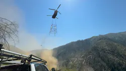
In June 2025, the team began tower erection. The team used exclusively helicopter construction to build the new tower per design. After transferring the shield wire and conductor to the new structure and splicing in additional wire to maintain appropriate tensions, the legs of existing 15/115 were cut off at the stubs and the entire tower was removed from the landslide area via helicopter.
The crews also removed the existing tower 15/114 from the corridor. After transferring the towers to a nearby laydown yard, crews disassembled and recycled them. The line was re-energized, and construction was complete before additional rainfall progressed the landslide further.
In just eight months, the team was able to successfully design, permit and construct a solution to protect the safety and well-being of the public and ensure reliability of the 230 kV transmission system. As the climate continues to change, more projects like these may become necessary. In the transmission industry, it will be critical to be ready and prepared to tackle the world’s toughest challenges.
Lessons Learned from the Landslide Project
After the crews completed construction and the engineers finalized as-built documents, the team met to discuss lessons learned and celebrate the achievements of this challenging project. The main takeaways included the following:
1. Sensitivity of PLS-CADD tensions. As the tower began to deflect and deform, it became increasingly difficult to accurately determine the tension in the shield wire. For sensitive analysis, field verification is recommended. Even slight changes in clipped wire length can have massive impacts on wire tension.
2. Value of frequent inspections. Without PG&E’s frequent LiDAR inspections, it would have been difficult to identify the severity of the landslide. Continuous monitoring by field crews, along with analysis by design staff, helped the team provide evidence to promote the project to emergency status and expedite installation.
3. Lead times. In a booming transmission market, emergency projects must order long lead material as soon as possible. Delivery of the tower steel proved to be critical path for installation. Had the team waited to order tower steel until design was complete, the reliability of the transmission system may have been compromised.
4. Spare parts. Having spare parts in stock, such as the hardware installed to reduce shield wire tension, was critical for temporary mitigation efforts. Maintaining additional insulators, hardware and conductor in nearby warehouses was also critical to ensure no construction delays.
About the Author
Austin Holtorf
Austin Holtorf is a professional engineer and assistant department manager for Overhead Transmission, Transmission & Distribution Services, at Burns & McDonnell, the engineering firm on the project.
Handel Chavez
Handel Chavez is an Electrical Engineer and the Electrical Supervisor, Transmission Line Engineering (North), for Pacific Gas & Electric.
Adam Nguyen
Adam Nguyen is a professional engineer and the Senior Civil Project Engineer, Transmission Line Civil Engineering Department, for Pacific Gas & Electric, the asset owner on the project.
Related
 dreamstime_xxl_226114802_1
 Because of the height of the towers and reach needed to install the top crossarms, a 900-ton crane was necessary, which also served as the primary steel erection crane; the 800-ton crane was used to transport personnel to minimize worker fatigue and assist with picks, when necessary.