Since 1970, Holyoke Gas & Electric Department has installed approximately 106 two-way and three-way vacuum switches throughout the extensive manhole and duct system in Holyoke, Massachusetts, U.S., to isolate faulted sections and restore power to as many customers as possible. In the last few years, the utility has experienced failures of the accessories attached to the switches.
In addition, during outages that required fault isolation, access to these switches has been difficult and time consuming because, in some cases, utility personnel had to pump manholes prior to operating the switches or the switches were not quickly and easily accessible, which prolonged the outages. These failures create electrical, mechanical and arc flash hazards to line personnel who enter the manhole to operate these switches.
To improve worker safety and system reliability as well as provide full supervisory control and data acquisition (SCADA) functionality, Holyoke Gas & Electric (HG&E) embarked on a program to remove all vacuum switches from manholes and find solutions that were either pad-mounted or submersible. To reduce its system average interruption duration index (SAIDI) and system average interruption frequency index (SAIFI) averages, HG&E will refeed side taps previously fed directly off the underground main from five-way automatic switchgear. This will minimize the impact of faulted cables or equipment located on a side tap. Having this automatic transfer capability also will provide a second source that automatically switches upon loss of source.
Requirements Fulfilled
Switchgear had to meet the following list of requirements for HG&E to consider purchasing it:
- Must be capable of interrupting 12.5 kA of symmetrical fault current
- Must fully be SCADA capable to operate a switch remotely and communicate by DNP3 or IEC 61850 standards to ensure, if communication protocols change, the switchgear can accommodate the change without HG&E having to install additional equipment
- Must have visible breaks on all ways so line personnel can physically see a switch is in the open position prior to commencing work
- Must have single-phase fault interrupters on each outgoing way, so three single-phase loads can be connected to the switch such that, if one single-phase load is faulted, the other two single-phase loads will not be interrupted
- Must contain three current transformers per way for overcurrent sensing
- Must have three vacuum interrupters for each incoming way so, when a bus failure occurs or as backup in case an outgoing way fails, the switchgear will operate during a faulted condition
- Must contain three potential transformers per incoming way to facilitate source transfer upon loss of source voltage
- Must be programmable for auto-transfer but have the capability to be reprogrammed for other setups such as a lateral switch
- Must have a motor operator for all ways so each way can be operated remotely or locally
- Must have a SEL-487E relay from Schweitzer Engineering Laboratories Inc. (SEL) to handle all the digital, analog inputs and programming
- Must be able to function on 15-kV wye or 5-kV delta systems
- Must be single sided for both pad-mounted and submersible versions
- Must be able to control the submersible version by a pendant control or SCADA
- Must have the exterior tank made of type 304L stainless steel
- Must be capable of having test voltage applied to one side of a disconnect switch and system potential to the other side of the same disconnect switch, to test for cable faults without having to remove the 600-A T-body connectors
- Must have a 120-VAC to 24-VDC charging system with an automatic transfer relay for loss of source power.
Several manufacturers met most of these requirements, but only Trayer Engineering Corp. met all of them. Trayer has been building pad-mounted and submersible switchgear successfully since 1962, and it was able to customize the switchgear for HG&E’s specifications.
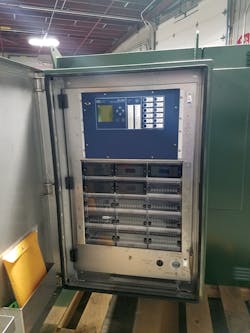
SEL 487E relay and test switches. The relay is highly adaptable and can protect all five ways.
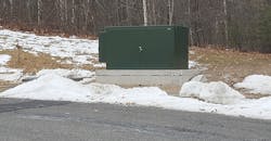
The pad-mounted switch is 104 inches long x 57.5 inches wide x 61 inches tall (2.6 m x 1.5 m x 1.6 m) and weighs 7625 lb (3459 kg). The size of these units made finding locations to install a pad-mounted switch in the city of Holyoke a challenge. So HG&E chose to purchase a submersible unit, identical in function and tank size, for vault-mounted applications in the more densely populated areas of Holyoke.
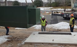
Placing the switchgear on the customized pad
Vault Version
The submersible unit has the same functionality and operability as the pad-mounted unit. It is designed to be installed in a vault with the motor operators and switch handles facing upward. The vault is shallow so line personnel can access the motor operators, switch handles and switch connections. The vault has a second compartment to house the relay, batteries, fiber box and pendant control. Customized for Holyoke switchgear applications, the vault also has three diamond-plated skid-resistant hatches, with pneumatic springs to open the hatches.
The pendant control is connected to the SEL-487E relay cabinet by a 20-ft (6.1-m) lead and is stowed inside the vault. It is used when a local operator needs to perform switching functions. The control displays the system status such as the status of each way, whether the unit is locally controlled or remotely controlled, whether the system is in automatic transfer mode or manual mode, and whether both source ways have voltage present or not. The operator can operate each motor operator, make the switch operable locally or remotely, and turn automatic transfer function on and off by the pendant control.
Control
The SEL-487E relay was originally designed for classic high-reliability substation transformer protection applications. Because of its highly adaptable input/output-intensive capability, the relay was chosen for this specific distribution automation function. Although this application was not considered by the manufacturer, it has been used for this type of application by other utilities.
The customization of SEL-487E’s firmware takes advantage of the control’s ability to protect five separate three-phase circuits simultaneously. This enables the same control to provide high-speed transfer functions, fiber or radio communications, an optional geographical positioning system (GPS) clock and true synchrophasing to ensure closed transitions for both feeds are completed in exact synchronicity relative to the phasor. However, HG&E will not be using a closed transition for the automatic transfer function.
Switch Installations
The first switchgear was installed at a commercial park with a 1-MW solar facility. Prior to the switch installation, if an outage occurred that affected these customers, HG&E would have to send a line crew to pump the vault with the submersible switch inside and operate the switch to make a tie to another circuit. The utility removed an older submersible two-way tie switch and replaced it with a five-way switchgear.
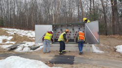
Ensuring the switchgear is level and unharmed from its journey.
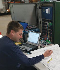
Senior Electronics Technician, Lafe Sawyer, reviewing logic diagrams and putting switch and relay through its paces.
Today, in a similar outage situation, customers only experience a momentary interruption. Furthermore, if a customer in the commercial park has a fault on the feed to their transformer, the only one affected by the failure is the customer with the fault. Only the breaker to that specific customer would open, thus increasing reliability and decreasing the number of customers impacted. One outgoing breaker was reserved for the 1-MW solar facility to isolate the generator for emergencies and equipment maintenance so other customers are not affected.
In 2019, HG&E is planning five-way switchgear projects, including the installation of two-pad mounted switchgear with automatic transfer for a small section of the city with a lot of load. Each half of the city section will have two feeders supplying a single five-way switchgear. Outgoing ways will each provide power to several transformers. Additionally, the transformers will be looped to enable the utility to back-feed in case of a transformer failure or cable failure. This project will eliminate 12 submersible vacuum switches and increase reliability.
In addition, a single submersible unit is scheduled for installation near a large municipal customer. The outgoing ways of this switchgear will feed the municipal site, a large commercial customer, and three single-phase loads through the single-phase breakers from a single switchgear way.
HG&E plans to eliminate every submersible vacuum switch located in manholes over the next 10 years through a variety of methods. In areas where overhead poles and wires are available, the utility will install air brake switches or sectionalizing switches to replace the vacuum switches. In underground areas, traditional two-way or four-way air-insulated switchgear, terminal cabinets or five-way switchgear will be used. The decision on which underground method to use will be based on several factors, such as the availability of an alternate feeder and the amount of customer load to be protected. HG&E plans to eliminate 18 submersible vacuum switches in 2019.
For more information:
HG&E | www.hged.com
SEL | www.selinc.com
Trayer | https://trayer.com
About the Author
Carl.Peterson
Carl Peterson is a senior electrical engineer at Holyoke Gas & Electric Department. He is a retired naval intelligence officer with a bachelor’s degree from Texas Tech University and a master’s degree in power systems from Worcester Polytechnic Institute. He currently is working on a second master’s degree in electrical and computer engineering from WPI. He has worked in various capacities at two investor-owned utilities.
