The New Grandview GIS Substation Is Better
Glendale Water & Power’s first air-insulated Grandview substation was built in 1930 and had been serving more than 1000 residential customers and 400 industrial and commercial customers in the Grand Central business district of the San Fernando Corridor in Glendale, California, U.S. However, the municipal-owned utility’s Grandview substation did not have capacity for the expected load growth in this part of Glendale, and its air-insulated switchgear (AIS) occupied a lot of precious real estate.
The adjacent Western substation is operating at 69 kV/12 kV, while the existing Grandview substation was at 34.5 kV/4 kV. This limited the utility’s ability to switch load between the stations during peak summer demand seasons in case of emergencies or during required maintenance periods.
To resolve these issues, Glendale Water & Power (GWP) replaced the existing substation with a new substation of higher capacity and compatible operating voltages. Equipped with gas-insulated switchgear (GIS), the new substation was completed in 18 months at a cost of approximately US$15.1 million. In addition to this, the cost for building the new distribution feeder getaways and the transmission lines was about $3 million. The project was completed within budget and on schedule.
Rebuilt Substation
Located in the western portion of the City of Glendale, the Grandview substation was equipped with two step-down transformer banks — from 34.5 kV to 4.16 kV — that had a total capacity of about 22.5 MVA and 14 4.16-kV distribution feeders, including three inactive feeders. With a height of about 25 ft (7.6 m), the existing air-insulated switchgear rack was not visually pleasing. Also, it occupied a lot of real estate.
GWP rebuilt the substation using a unique design that improved the substation aesthetics while enhancing the reliability of the electric power supply throughout the neighborhood. The new substation has enough capacity to meet the requirements of future load growth. This facility provides a cost-effective solution with sufficient redundancy to ensure highly reliable electric service during peak load periods.
The new substation is energized by two 69-kV circuits of underground cables from the Kellogg switching substation and the Western substation. In the future, a third circuit will be energized by the Montrose substation. Each circuit is designed to carry the full load of the Grandview substation, providing redundancy and stability of power supply to the Grandview substation.
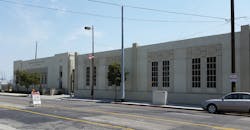
The existing Grandview substation building was reinforced and upgraded to meet the current seismic codes, without impacting the unique architectural features of the historic building. Aesthetically pleasing walls were built around the substation to reduce the visual impact and provide a less-intrusive design in the commercial environment of the existing Grandview substation.
For the most part, the new GIS substation was a turnkey design-build contract. The primary contractor, Beta Engineering, provided the engineering design, supplied the equipment for the GIS substation and carried out the installation.
Beta Engineering based its designs on GWP’s substation panel layout standards, alternating-current/direct-current (AC/DC) schematic standards and panel wiring diagram standards. The designs were reviewed and approved with corrections, as needed, by GWP electrical engineering at 65%, 90% and 100% completion. All equipment drawings were reviewed and approved with corrections, as needed, by GWP electrical engineering prior to the equipment being manufactured.
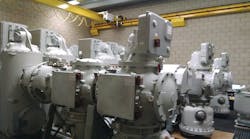
Relay protection and supervisory control and data acquisition (SCADA) remote terminal unit (RTU) programming was performed by GWP’s electrical engineering team. The GIS, the major component of the substation, was fabricated in Germany by Siemens, and then assembled and installed at the Grandview substation.
Beta Engineering installed the conduits and cable trenches inside the substation boundary, while GWP crews completed all duct work in the public rights-of-way. GWP crews completed all transmission and distribution wiring, including cable pulling and termination of the 69-kV and 12-kV cables to the respective switchgears.
Construction Challenges
Like many large construction projects, this project had to overcome a few challenges. The challenges, however, were no match for the effective project management and cooperative teamwork displayed by all parties involved. Weekly project review meetings were held to discuss issues and find solutions. The challenges were overcome by timely decision making to obviate any delay in completing the project.
The first task was to reconstruct the electric distribution system in the area served by the original substation to prepare it for the new operating voltage of 12.47 kV. This involved rebuilding more than 10 circuit miles (16 km) of overhead and underground distribution system. The reconstruction for 12-kV operation was completed in 2009.
The next step was to cut over these areas to the adjoining feeders from the Western substation and decommission the original substation. The existing Grandview feeder service areas were cut over to the Western substation feeders in 2014.
The original substation was energized by the 34.5-kV Glendale–Grandview North and Glendale–Grandview South lines. A major portion of the 34.5-kV Glendale–Grandview North line and 69-kV Kellogg–Western line 2 shared the same pole lines. This pole line had to be rebuilt and reconfigured to remove the 34.5-kV Glendale–Grandview North line and build the 69-kV Kellogg–Grandview line. To energize the new substation using 69 kV, the existing 69-kV Kellogg–Western line 2 was modified to the Kellogg–Grandview line and Grandview–Western line.
Most of the civil construction work in the public right-of-way and all the overhead and underground construction work was performed by GWP crews. A major task was to install the required substructures for the 69-kV subtransmission lines as well as the 12-kV distribution feeder getaways. A separate substructure system was installed for the transmission and distribution lines. It was a formidable task to find room along San Fernando Road, which has a lot of existing underground utilities. The duct bank had to be installed up to 15 ft (4.5 m) deep in certain sections to clear the existing water lines and other utilities.
This project required installation of three new distribution vaults for northbound feeders along with two transmission vaults and the associated substructure. Two distribution vaults and the associated substructure were installed for the southbound feeders.
Controlling traffic on this busy thoroughfare also was a major challenge for the project team. Frayed nerves of the commuting public had to be soothed as the public was weary of frequent construction on this street. This was accomplished by staging the construction in different phases with at least one lane always open in both directions. Public outreach efforts were undertaken by sending mailers to the adjoining communities, setting up meetings with the public and publishing information on the city website. The only time the street was partially closed to traffic was when the two power transformers were installed using a heavy crane. This work was completed in about five hours.
A portion of the substructures were installed in 2013 in conjunction with the city public works department’s storm drain project. Installation of the electric conduits under the railroad tracks, at a depth of about 25 ft (7.6 m) under the tracks, in huge steel pipes was a major challenge. Another significant obstacle was the existence of two abandoned 26-inch (660-mm) gas lines with asbestos contaminants that conflicted with the proposed substructures. With effective project management and coordination with the Southern California Gas Co., these gas lines with hazardous materials were removed safely.
Project Teamwork
Proper coordination between the GWP project team and Beta Engineering, and their subcontractors, was a key factor in completing this project in a timely manner. The cooperation of other utilities impacted by this project, especially the gas utility, is worth mentioning. The public outreach effort by the project team was quite successful as evidenced by the very few complaints from the public. The new GIS substation provides GWP with more capacity, more reliability and flexibility in the operation of its electrical system.
The project broke ground in January 2015 and was commissioned in July 2016. The final cost of the project was $15.1 million, which was within budget. Completing a project of this enormity and complexity within budget and on schedule was a major feat for the project team. This was made possible through good project management by GWP, great teamwork by all parties involved and a thorough understanding of project goals and existing site conditions by Beta Engineering. Beta Engineering’s prior experience with GWP in installing the Glorietta GIS substation in Glendale also helped tremendously in executing this project.
Sidebar: Grandview Substation Salient Features
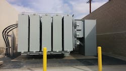
- Two 15/20/25-MVA, 69-kV/12.47-kV transformers with an option to add a third transformer protected by firewalls, and provided with oil containment that meets federal and state spill prevention, control and countermeasure requirements.
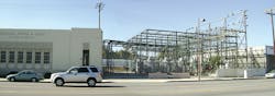
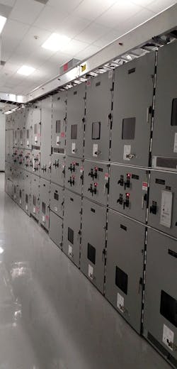
- 69-kV GIS in six-breaker ring bus arrangement with six bays (two of which are for future expansion), with its local control cabinet, installed in a new building.
- Two circuits of 69-kV underground cables for 69-kV Grandview-Kellogg line and 69-kV Grandview-Western line, with provisions for one additional circuit of 69-kV underground cables for the future 69-kV Grandview-Montrose line, directly terminated to the 69-kV ring bus.
- 69-kV primary lines feeding transformers routed from 69-kV GIS breakers through underground duct bank to transformers.
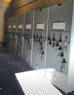
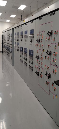
- 12.47-kV cables from transformer secondary side routed through cable trench and conduit system to 12.47-kV arc-resistant switchgear panels for bottom entry in existing building.
- Two sectionalized double bus, double-circuit breaker 12.47-kV arc-resistant AIS switchgear lineups, one for each transformer, located in an existing building.
- Six 12.47-kV outgoing underground distribution feeders with option for three additional feeders.
- Sectionalized double bus for improved flexibility to switch and isolate circuits for maintenance.
About the Author
Hovsep Barkhordarian
Electrical Engineer
Hovsep Barkhordarian is an electrical engineer in charge of the substation engineering group at Glendale Water & Power. He was the project manager for this project. He holds an MSEE degree from California State University, Northridge, and is a registered professional electrical engineer in California.