The Japanese government established goals for introducing renewable energy sources of 28 GW in 2020 and 53 GW in 2030. The 2030 figure is equal to 30% of current peak demand. In 2010, a feed-in tariff was introduced that resulted in rapid commissioning of large-scale industrial and residential photovoltaic (PV) systems.
Since all nuclear power plants have not operated following the Great East Japan Earthquake in 2011, all renewable energy sources are now regarded as an acceptable alternative power. In September 2014, the total capacity of PV installations was 18 GW, and the total capacity, including accepted and planned PV, is estimated to be 69 GW, well in excess of the government 2030 goal. Therefore, Kansai Electric Power Co. Inc. (KEPCO), the second-largest electric power utility in Japan, has been working on the challenges arising from the rapid introduction of PV systems.
Distribution System Management
Japanese utilities started to introduce distribution automation systems (DAS) in the 1990s to remotely control sectionalizing switchgear. The major functions of the first DAS was to automatically detect the faulty section and to remotely energize the healthy section of the network. The DAS could also identify the faulty section using a step-by-step closing operation of each sectionalizer, and control of remote switchgear enabled reconfiguration of the distribution network to energize the healthy section from other feeders.
In order to realize these functions, the switchgear installed on the distribution network is used daily and is a contributing factor for reducing the annual average outage time in Japan to just 14 minutes.
Power-Quality Maintenance
In Japan, the low-voltage network is 100/200 V. In accordance with the Electricity Business Act, it must be maintained in the range of 101 ±6 V or 202 ±20 V. This is less than the IEC standard, which allows a ±10% margin. In addition, the Japanese medium-voltage distribution network is mainly 6.6 kV, which is a lower voltage than most other countries. These lower voltages are more sensitive to voltage fluctuations.
To maintain the voltage profile within the specified range, KEPCO has installed step voltage regulators (SVR) on medium-voltage distribution lines. They autonomously control the secondary voltage on the basis of either a time schedule or calculation from the through current and control parameters. The operating schedule or control parameters are determined based on voltage-profile analysis and the recorded load measurement data in the DAS.
Photovoltaic Impact
Photovoltaic penetration introduces various impacts to power system management, such as voltage and frequency fluctuation and surplus power at times of light load. Because of the wide penetration of middle-scale PV that typically has an installed capacity greater than 500 kW in the distribution network, the line voltage can be raised by reverse power flow caused by fluctuating weather conditions. This phenomenon requires countermeasures for the distribution network voltage management.
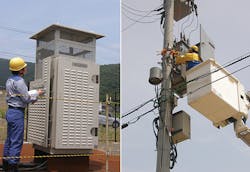
In response to these problems, in recent years, Japanese utilities and manufacturers have developed advanced distribution management systems. Conventional switchgear is being replaced with new switchgear with three-phase internal sensors (3S-SW), which can measure three-phase voltage, current and phase angle on distribution lines. These measurements are uploaded to the supervision and control center via dedicated communications networks. They are widely used for recording the overall power flow and voltage profile in distribution lines.
Some manufactures and research institutes have constructed testing facilities, to simulate the operational characteristics of the grid, connected with a large number dispersed energy resources. These approaches are expected to lead to accurate estimation of voltage and current to enhance the advancement of voltage management technology.
Advancement of Voltage Control
Each step voltage regulator controls its secondary voltage to absorb voltage fluctuations at intervals ranging from around 50 seconds through to a few minutes, according to the autonomous control parameters determined from consumers’ power-usage/voltage-profiling data. This control strategy is not sufficient for the complicated and dynamic voltage fluctuations in the distribution system that can be caused by PV. For low-voltage-class rooftop PV installations, the output fluctuation, to some extent, can be smoothed because they are distributed.
Conversely, the output of industrial PV installations, which are much larger than typical residential installations, cannot be smoothed because the output is large and concentrated. Consequently, the distribution line voltage can fluctuate rapidly and exceed the performance range of conventional regulators.
As the first step to solve this problem, KEPCO uses the measurement data of line current, current direction and the voltage magnitude of each phase by 3S-SW to estimate the voltage profile more accurately using the remote-controlled SVR to set the optimum transformer tap position or control parameters according to the measured data. The next step for KEPCO is to improve voltage control in order to cope with rapid voltage fluctuation caused by PV.
Power Electronics Technology
KEPCO is now developing and testing two power electronics-based control devices. One is static var compensator (SVC) connected in parallel in a distribution line. The semiconductor device will supply reactive power into the connected line instantaneously to compensate rapid voltage fluctuations.
A further development is the thyristor-type step voltage regulator (TVR) connected in series in a distribution line. It controls its tap position to keep the secondary voltage in phase with the SVR, but its control is electronic as opposed to the non-mechanical SVR control. The significant advantages of the TVR are the fast response and wear-free tap movement, thereby eliminating mechanical contact.
Demonstration Project
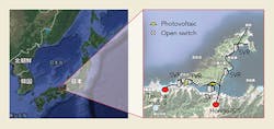
KEPCO constructed a PV demonstration project to measure the impact of middle-scale PV and to evaluate the performance of the new devices before in-service use. This trial environment has two 500-kW PV systems connected to a 6.6-kV overhead distribution line in the Wakasa area, located north of the Kansai region.
One feature of the project is the use of in-service distribution lines in various real-time conditions such as daily load variations and high-voltage transmission affection. The test facility has the flexibility to consider various conditions because there is a wide variety of the actual network topologies and PV interconnection points. The demonstration site has two distribution lines supplied from adjacent substations, so the network topology can be changed easily by switching operations. Thus, the demonstration site allows the middle-scale PV to be in circuit at various positions on the distribution lines between the two substations.
The impacts of PV and the voltage-control performances were evaluated with measurement data from some 3S-SW
installed at the source substations, PV interconnection points and other distinctive positions on the distribution lines. The 3S-SWs measured the current, voltage and phase angle every second in some periods characterized by the load curve, PV output and weather.
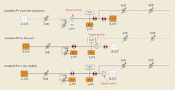
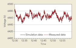
Simulation software has been developed to estimate and evaluate the voltage fluctuation and load profile at every second. KEPCO can compare the actual measurements of all the variables with simulation results, providing the opportunity to improve the accuracy of the software. Initially, the current and voltage fluctuation were measured and analyzed for three different PV interconnection positions relative to the source side of the distribution line:
• One 500-kW PV connection at the source side of the distribution line.
• One 500-kW PV connection at the remote end of the distribution line.
• Two 500-kW PV connections at the remote end of the distribution line.
The measured characteristics included various PV outputs and load curves under the normal operation with conventional voltage regulators. The results confirmed that the voltage regulators operated satisfactorily and the maximum voltage fluctuation was within the acceptable range for the distribution operation, even in the worst case. KEPCO also measured and analyzed a further test, whereby two 500-kW PVs were connected to the middle section of the same distribution line.
As the accuracy of the simulation software was continually monitored, KEPCO was able to confirm that the network voltage could be accurately correlated to the network power factor at the feeding point of the distribution line and the PV output measured by 3S-SW.
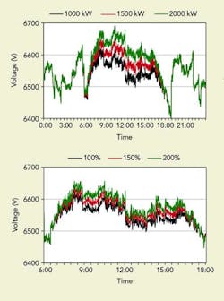
By using the software, the distribution network condition with various amount of PV, KEPCO was able to confirm that the variation in voltage fluctuations was directly proportional to the kilowatt capacity of the PV plant connected to the distribution line. Also, the company confirmed that the voltage fluctuation increased according to the distance between the source substation and PV plant.
New Voltage Control Devices
KEPCO set the control parameters of the conventional SVR according to the voltage-profile analysis from previous annual load measurement data in the DAS in order to adjust both maximum and minimum values of line voltage within the proper range. Although these parameters optimized the annual performance of SVR, they were not consistently accurate, because the annual maximum and minimum voltages could not be observed in the same short time period.
The remote-controlled SVR offered a solution to this problem, which allowed frequent parameter readjustment from DAS remotely. KEPCO tried annual, seasonal, monthly and daily parameter readjustment according to past load profiles, simulating operation of the remote-controlled SVR with each parameter before confirming that the monthly parameter readjustment was the most accurate. The operation of the remote-controlled SVR by the simulation software will continue in order for applications on actual distribution networks.
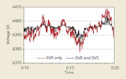
The SVC is a type of system voltage regulator that is similar to the SVR, but the SVC compensates for rapid voltage fluctuation in a distribution line by rapid reactive power regulation. KEPCO has already installed a large number of SVR units on the distribution network, but these units cannot compensate rapid voltage fluctuations. However, the combination control can be provided by SVR and SVC, whereby the SVR compensates long-cycle fluctuations by load and SVC compensates short-cycle fluctuations PV output.
In order to investigate the effect of rapid fluctuations of the PV generated output, KEPCO analyzed the transition of voltage fluctuation. It was concluded that the voltage fluctuation was stabilized in about 5 minutes, so this time period was used as a parameter for the SVC to compensate the shorter cycle voltage fluctuations, also in 5 minutes.
TVR units are primarily installed at the branch points/nodes in a distribution line supplying residential customers to compensate local voltage fluctuations caused by a large number of residential PV installations in the area. In the demonstration project, a TVR was installed on the interconnecting point of the residential PV. The control effect was evaluated by actual measurement and simulation software, and the results proved there was satisfactory compensation of rapid voltage fluctuations.
Voltage Control Enhanced
The objective of the demonstration project was to advance the voltage control of the distribution network to cope with the increasing penetration of PV power systems. The PV impact on distribution lines and the improvement caused by a new voltage control approach has been undertaken on an actual distribution network in the Wakasa area.
There are three key results of this demonstration project:
• The impact to distribution network caused by PV, such as voltage fluctuations, was confirmed.
• KEPCO developed the simulation software that made it possible to simulate distribution network conditions accurately while changing capacity or location of PV or voltage regulators.
• KEPCO was able to confirm that new voltage regulators, such as remote-controlled SVR, SVC and TVR, were effective for PV and that combination control could be realized.
KEPCO plans to continue the demonstration, changing the distribution network topology in order to achieve the optimum combination of voltage regulators and the advancement of control method depending on the capacity and the location of photovoltaic.
Additionally, KEPCO is considering other methods to cope with the increased penetration of dispersed energy resources by using smart meters, optical fiber network and weather information such as satellite pictures.
Acknowledgements
The authors wish to thank Mitsubishi Electric Corp., Hitachi Ltd. and DAIHEN Corp. and all of those who have contributed and cooperated in the test environment construction and control development for the Wakasa demonstration project.
Takaharu Ito joined Kansai Electric Power Co. in 1992, working in distribution network planning. Ito is now senior manager of the distribution group (smart grid) in the power system division, where he supervises the development of smart grids, especially smart meters and distribution automation systems.
Manabu Inai joined Kansai Electric Power Co. in 2004, working on the planning and development of the distribution network before being appointed assistant manager of the distribution group (smart grid). He is now responsible for investigating smart grid technologies and developing methods of using smart meter data.
Kentaro Fujimoto joined Kansai Electric Power Co. in 2001 and has worked on developing equipment related to distribution networks. Fujimoto is currently responsible for developing advanced equipment for distribution automation systems, including switchgear with sensors and voltage regulators.
