Drilling Past the Limits
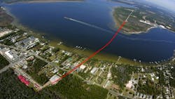
PowerSouth Energy Cooperative needed a new 300-MVA, 115-kV transmission line to feed Orange Beach, Alabama, U.S. The new line also could be a networked line serving several other substations in south Baldwin County, an area served by Baldwin EMC. Approximately 5 miles (8 km) of the new transmission line was typical overhead construction designed for a Gulf of Mexico coastal environment. However, approximately 6,500 ft (2 km) of this new transmission line had to be installed under the Intracoastal Waterway, Wolf Bay, Alabama Highway 180 and PowerSouth’s energized 115-kV Florida Avenue substation.
PowerSouth used horizontal directional drilling (HDD) for the underground cable duct installation between the Sapling Point area and the Florida Avenue substation. Although finding the right sites to develop an acceptable HDD route proved challenging, PowerSouth knew it needed to get this right to improve transmission reliability in the Orange Beach/Gulf Shores service area.
Duct Installation
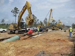
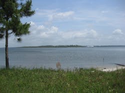
Sapling Point to the north is mostly undeveloped, making HDD entry and exit site selection relatively easy while also providing room for back-string fabrication. The back string is an assembly of pipes forming one continuous length required to pull in the drilled hole without stopping.
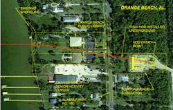
Unlike Sapling Point, the Florida Avenue site selection proved significantly more challenging. New overhead transmission lines were not an option, so only sites immediately adjacent to the substation could be considered. Also, property to the east and west of the substation was unavailable, making areas immediately to the north and south the only sites available.
During the initial inspection, the area north of the substation was preferred because this site was larger and closer to Sapling Point. Also, this area did not require drilling under the energized Florida Avenue substation or work next to the 115-kV energized overhead transmission lines. Unfortunately, a detailed design analysis determined this site was not an option. Drill clearances under the road, existing utilities and the bend radius required to develop a route between the Orange Beach Library and the Orange Beach Senior Activity Center were unacceptable.
Therefore, the site south of the substation was the only remaining possibility to develop an acceptable HDD route. Unfortunately, this site required drilling and cable installation under an energized substation, increased cable length and provided a work area significantly smaller than typically required for HDD operations. However, this site allowed the design of an HDD route between Florida Avenue and Sapling point if cable and installation challenges could be addressed.
The Challenges Addressed
One of these challenges was to develop a duct system capable of making the 6,131-ft (1,869-m) HDD pullback. High-density polyethylene (HDPE) and polyvinyl chloride (PVC) pipes were considered for the single-conductor 115-kV cable raceways with the wellbore and back-string modeled to develop pullback forces. This model indicated it may be possible to install the HDPE or PVC bundle, but forces could be close to the maximum allowed. Unfortunately, actual pullback forces would not be known until installation, which was then too late to modify the design. This concern was addressed by adding a 36-inch (0.9-m)-diameter steel casing to the design.
The steel casing significantly increased the allowable pullback forces if frictional forces turned out to be greater than anticipated. This decision paid huge dividends when the casing got stuck during initial pullback, with only approximately 1,000 ft (304 m) in the hole. This required the back string to be extracted before reworking the hole and completing the pullback. Without the added insurance provided by the steel casing, much of the back string and most, if not all, of the hole would have been lost.
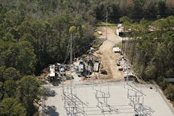
Before drilling under the energized 115-kV substation, a 60-inch (1.5-m)-diameter steel casing was installed to minimize potential impacts to the substation during drilling. This was the only time the substation was de- energized and coordinated with substation upgrades to accept the new 115-kV transmission line. However, even with the 60-inch casing in place, drilling under an energized 115-kV substation created safety challenges that had to be addressed.
The concern was steel casing in direct contact with the substation ground grid was also connecting the drilling equipment to the substation ground grid. An electrical failure or lightning strike in or near the substation would elevate ground grid voltages and create a personnel shock hazard around the drilling equipment. This safety hazard was addressed by installing a temporary ground grid designed to IEEE Standard 80, the “Guide for Safety in AC Substation Grounding,” under each work site and tied to the substation grid with all equipment bonded to the ground grid.
With the 60-inch casing in place under the substation, crews removed soil from the casing and installed a 16-inch (41-cm) centralizer pipe. The centralizer pipe kept the drill string in the middle of the 60-inch casing during boring and ream pullback operations required to enlarge the drilled hole for the 36-inch steel casing pullback.
However, the 6,131-ft-long drill created another challenge. Directional drilling starts to lose steering capability after approximately 4,000 ft (1,219 m), depending on soil conditions, and the Wolf Bay crossing required a 6,131-ft drill. PowerSouth addressed this concern with the HDD intersect method. This requires drilling from both sides with each drill meeting close to the middle or, in this case, approximately 3,100 ft (945 m) from each end.
Cable Installation
Drilling from separate drill rigs at opposite ends and meeting in the middle requires knowing the precise location of each bit at all times. Magnetometers located behind each bit, and capable of detecting the magnetic field from a wire placed between entry sites and along the design route, provided exact drill bit locations. Once the drill bits met in approximately the middle of the 6,131-ft drill, the Sapling Point drill string was backed out, followed by the Florida Avenue drill string, until both drill bits exited at Sapling Point.
The Sapling Point drill rig was then removed with the Florida Avenue drill rig remaining to pull back reamers enlarging the hole, the 36-inch steel casing and the HDPE bundle. Drilling mud, a mixture of naturally occurring Bentonite clay and water, not only lubricated the drill string but also helped to remove cuttings while maintaining the structural integrity of the hole.
With the hole complete and reamed to 48 inches (1.2 m), the steel casing was pulled into the hole. The casing was flooded with water when entering the hole, making the casing almost neutrally buoyant in the heavier drilling mud and minimizing pullback forces. The pulling-head design of the HDPE bundle allowed water to flood the HDPE bundle on entry, making it almost neutrally buoyant and easy to install. This made what would have been an impossible HDPE installation an easy pullback.
Thermal grout was then installed in the annular space between the HDPE pipes and steel casing. However, because this installation approached the twice-previous installation lengths, its benefits were not considered in cable ampacity calculations. One of the lessons learned was thermal grout installation in extremely long duct systems is not only possible but practical, and may be considered in future designs to increase conductor ampacity.
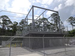
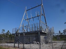
Termination structures required to transition the underground cables to overhead lines at Sapling Point and to a 4-inch (10-cm) aluminum bus at Florida Avenue were built. Designed to withstand a Category 3 hurricane storm surge, these structures also provided removable upper decks and a removable wall to accommodate current and potentially future cable installations.
HDD Design
The HDD design to provide a duct system for cable installation enabled the next major project challenge to be addressed. The challenge was developing a 300-MVA cable design that could be installed within the duct. A metal barrier, or sheath, required to prevent water ingress in high-voltage cable designs typically uses lead, the preferred sheath material. Unfortunately, calculated installation forces with a lead sheath cable design significantly exceeded the allowable cable-pulling tension and sidewall pressures. Clearly, a significantly lighter cable was required to reduce installation forces.
Sheath material options were investigated to reduce overall cable weight, with stainless steel selected as the material of choice. Stainless steel allowed a much thinner and lighter sheath and also reduced eddy currents, increasing cable ampacity ratings approximately 10%, a much-needed benefit. The stainless-steel sheath reduced cable weight from 45.2 lb/ft (67.2 kg/m) for a comparable lead-sheath cable design to
24.3 lb/ft (36.1 kg/m). The installation weight was further reduced to 14.5 lb/ft (21.6 kg/m) by taking advantage of Archimedes’ principle and filling each duct with water.
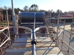
Installation forces were further reduced by coating the HDPE cable jacket with graphite, providing the added benefit of creating a ground plane on the outside of the cable, allowing hipot jacket integrity testing. A wax-based lubricant applied to the cable jacket during installation also reduced pulling forces. Finally, cable haulers placed between the cable reel and duct entrance at Florida Avenue reduced pulling forces by pushing. These haulers also had the capability of holding back on the cable. The first 800 ft (244 m) of duct was designed with a negative 12-degree incline. This created a concern the cable may slide into the duct under the force of gravity, causing over-payout of the reel and damaging the cable.
During this part of the installation, the haulers were required to hold back on the cable to maintain a controlled installation and eliminate this risk. Cable reel breaks also were added as backup protection to prevent over payout of the cable from the reel. Once the cable stopped sliding into the duct, the cable haulers were used to push, reducing the Sapling Point cable winch pulling forces. This installation maintained less than 10,000-lb (4,500-kg) pulling forces on all cables, providing a significant safety margin below the 38,000 lb (17,200 kg) allowed.
Unfortunately, the increased cable ampacity achieved with a stainless-steel sheath did not reach the required 300 MVA. Because 2,500 sq mm (4,933 kcmil) copper conductor was the largest available, another change in cable design was required. Alternating current tends to concentrate near the conductor surface, creating a phenomena known as skin effect. To take advantage of this phenomena and increase the current capacity, several of the 305 individual copper strands forming the 2.5-inch (0.06-m)-diameter conductor were coated with an insulating enamel.
The cable design change significantly increased the overall surface area of the copper conductor. This change created a design capable of installation that met the 300-MVA requirements and provided an emergency rating of 370 MVA and 1,858 A for 100 hours. Optical fibers placed within two stainless-steel tubes located just below the stainless-steel cable sheath are used for a distributed temperature-sensing system. This system provides real-time temperature monitoring throughout the entire cable length during operation.
Cable installation now required racking and preparation for termination. Racking is the coiling of cables on supports to provide extra cable for re-termination and accommodating cable movement. Calculations indicated 2-ft (0.6-m) thermal growth and 9-ft (2.7-m) cable snaking. Snaking is a thermomechanical phenomenon that occurs within the duct during load cycles. This required a racking system designed for a cable movement of 11 ft (3.4 m).
Because this was impractical, a cable ratcheting system was used. Cable ratcheting clamps are not common in the U.S. but have been successfully applied in Japan for more than 30 years. These clamps allow 200% calculated cable expansion and prevent cable from sliding into the duct during load cycles. This significantly reduced the racking and termination structure size.
However, before terminating the cables, insulation on the individual conductor strands had to be removed. This was accomplished by spreading the 305 individual copper strands, sand blasting and reweaving them into their original shape. This allowed crimp lug installation as required for the termination and connection to the substation at Florida Avenue and the new overhead line at Sapling Point.
The Unseen
One of the nicest benefits of this installation is what people do not see. The entire installation was essentially invisible during construction and remains invisible to the beautiful Orange Beach area and residents.
The success of this project hinged on the ingenuity of the engineering and project management team as well as on the support of the city of Orange Beach and the surrounding area.
Joe R. Armstrong ([email protected]) received a BSCE degree from the University of Alabama. After three years in consulting, he joined PowerSouth (formerly Alabama Electric Cooperative) as a transmission line engineer in the T&D engineering and construction group. Armstrong currently serves as transmission operations and maintenance manager in PowerSouth’s T&D operations and maintenance group. He is a registered professional engineer.
Arthur J. Smith III ([email protected]) received a BSEE degree from Tulane University. He joined Waldemar S. Nelson and Co. Inc., a New Orleans consulting engineering firm, in 1975 while attending university and continued on after graduation, progressing through the ranks to his current position of senior vice president and manager of the electrical engineering department for the New Orleans office. He is presently the IEEE electrical safety committee standards chairman and executive committee member. He also is a member of the National Fire Protection Association International, Louisiana Engineering Society and National Society of Professional Engineers.
