Driven by a need for multidiscipline substation design and intelligent data capture, the U.K. and Ireland are moving toward 3-D substation modeling and building information modeling (BIM) implementation in the transmission sector. AECOM’s implementation of 3-D substation modeling enabled several early wins, including visualization of concept designs, improving delivery through increased quality and efficiency, and allowing multiple disciplines to work on a single source of truth.
Why 3-D?
The AECOM Power team’s move from the traditional 2-D world of T&D substation design to the 3-D world was fourfold:
- There was a client need.
- There was a need to improve the quality and efficiency of project deliverables.
- It would give AECOM a distinct edge over its competitors.
- It would streamline the project management processes and enable better interdisciplinary coordination.
Many of AECOM Power’s clients have been affected by the U.K.’s BIM initiative, as well as by increasingly stringent economic and sustainability controls. This has required many clients to move toward 3-D substation design and BIM implementation. There is a general consensus that 3-D substation modeling will significantly improve design, construction and operation of substation assets. The whole-life concept of BIM is especially attractive to utility owners and operators.
The use of 3-D modeling and the associated BIM software have enabled a more streamlined project management process, reducing checking and appraisal times. As a multidisciplinary consultancy, multiple teams are often working on the same project. The 3-D substation modeling allowed the various teams involved (such as electrical, civil and geophysics) to work on and contribute to a single source of truth, in turn improving efficiency and reducing errors.
First Experiences
The first experiences with 3-D design were with various 3-D models of a substation plant from a range of different sources. These were tested on a particular project involving 18 different plant options, all of which required 2-D layout and elevation drawings as well as a bill of materials (BoM) to be produced. AECOM quickly realized major savings with the 3-D model, as it allowed all the 2-D drawings and BoM to be produced automatically. It also allowed design iterations to be made to one source, without having to modify multiple drawings.
AECOM then decided to move toward a Bentley substation solution, as the library of electrical substation components was better than other platforms at the time. Furthermore, with its large and varied client base, AECOM learned interoperability was essential because of the range of technologies and software packages its clients prefer. Through a rigorous interoperability testing process with various software platforms, the company determined the selected solution was able to import and export various file formats successfully.
Greenfield Implementation
The 3-D substation modeling was implemented first for a greenfield site implementation and then for a brownfield site implementation. Once this had been done, it could be extended to more BIM-oriented solutions.
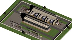
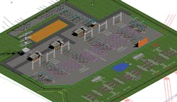
As expected, the new plant was easier to model. A 400/220-kV transmission substation was selected that involved a combination of disciplines — civil, electrical and architectural — and included both gas-insulated substation (GIS) and air-insulated substation (AIS) plant. As the project was at a concept design level, the majority of the electrical plant involved was generic, with the exception of the reactors, which were manufacturer-specific. Some of the 3-D plant models required in the design were already available in the software, while other components were developed in house. This allowed AECOM to build up a reasonable library of generic substation components, which were categorized by voltage, type and function.
One of the key features of this design was it included architectural and civil components (for example, the GIS buildings), which were created using non-Bentley software packages. These were referenced successfully into the model, further proving the interoperability capabilities.
The model was able to automatically produce 2-D layout and elevation drawings from the 3-D model. A BoM also was produced. The client and designers found the 3-D model useful for identifying construction and maintenance issues at an earlier stage than would traditionally occur, for example, ensuring adequate mobile elevating work platform (MEWP) access around the site.
Once the first substation was completed and delivered, a second greenfield site was trialed successfully. This involved a manufacturer-specific GIS plant. Subsequent to these initial greenfield implementations, AECOM was able to develop and refine the 3-D plant library further.
Brownfield Implementation
The next step was to begin implementing 3-D substation modeling at brownfield sites. Because of the inherent complications of brownfield design, this was done using a three-step process. The trial project involved adding three 400/220-kV transformers and associated switchgear to an existing 220/110-kV substation.
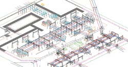
The first step was to design the 400-kV section in 3-D using the existing 2-D as-built layout of the substation as a base. The as-built drawing was the ground layer and the 3-D plant was built on top of it. Note, this did assume the as-built drawing was accurate, which is not always the case.
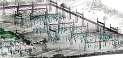
The second step was to undertake a full point cloud laser scan of the substation. Using this scan, it was possible to trace over the point cloud in 3-D to create 3-D components for the existing switchgear on site. The same computer-aided design (CAD) rules used in the creation of the generic 3-D components also were used in this second step; in turn, these were added to the 3-D component library. Once all relevant components in the substation were traced, the point clouds were deleted because they made the file unacceptably large.
The final output was then an accurate 3-D model of the existing substation. Note, it was determined from experience a point cloud accuracy of 10 mm was enough to produce a 3-D model with enough accuracy to suit the client’s needs. The third step was to combine the future and existing 3-D models. This resulted in a full 3-D model for the proposed substation.
The original 2-D as-built layout was removed, but it is interesting to note the 3-D model indicated the original 2-D layout was incorrect; one of the overhead lines was exiting the site at a different angle than expected. This was further proof as to the value of 3-D modeling.
BIM Applications
Once the 3-D substation models for both greenfield and brownfield sites had been developed, further BIM applications were trialed and implemented. By publishing an i-model from the 3-D substation models, the team was able to undertake accurate clash detection and drawing markups with the software package.
Using predefined clash detection rules, the design engineers were able to run clash reports for the entire substation. Clash detection rules were created for all disciplines and based on the clients’ standards or industry best practices, or a combination of both. Once the clash report was run, engineers were able to mark up the relevant issue on the 3-D model and send it back to the originator of that particular area of the model. This process ensured all aspects of the design were accurately checked, and the checking and approval process was efficient.
Some of the team’s clients requested various data attributes to be captured in the 3-D model, for example, plant weight, size, voltage, capacity, cost and carbon footprint. The engineers were able to determine this detail from datasheets and other tools such as carbon-footprint software, and attach it to each component in the models. Reports could then be run to determine the total cost of plant in the substation.
Furthermore, 4-D BIM was implemented, as some of the substations involved multiple stages or tight construction periods. By using this method, the construction period and methodology could be considered from the preliminary design onward. This allowed AECOM to identify construction issues early, which minimized rework and considerable delays during the detailed design and construction phases of the project.
Lessons Learned
As with implementation of any new technology, the AECOM Power team learned several lessons. One of the main lessons was related to a lack of experience in 3-D modeling within the team. This was an issue particularly in the beginning, whereby there were minimal 3-D-capable resources available for the projects. As a result, a training program was implemented so relevant staff were taught 3-D drafting. They could then build up their knowledge base over the course of various projects.
It also was difficult to obtain manufacturer-specific models of 3-D plants and equipment. Manufacturers were resistant to providing these models, possibly for intellectual property reasons. However, in the future, it may be possible to request high-level basic models, with a smaller amount of detail, as a part of the procurement contracts. These basic models also would help to reduce the size of the files, as the manufacturer-specific models are often large and contain more detail than required.
Finally, the AECOM Power team had difficulties convincing other teams in the business to adopt the idea of 3-D modeling. As the majority of projects are multidisciplinary, it was essential for multiple teams to contribute to the 3-D model, providing a single source of truth and, in turn, improving quality and efficiency. Apart from the initial resistance from other disciplines, there were varying opinions on the level of detail required, level of accuracy and layering conventions. To address this, AECOM formed a steering group and engaged various teams to form some guidelines and internal standards that addressed these issues.
Next Steps
The next steps for the AECOM Power team are to continue to build the full BIM capability, including 4-D to 7-D BIM and associated BIM standards. To aid this process, AECOM is rolling out ProjectWise, which will help with the management and quality processes when producing models and associated drawings.
Apart from further developing CAD staff competence in 3-D design, the aim is to expand the models to integrate with other platforms, for example, structural analysis software, ground-penetrating radar surveys and PLS-CADD. This includes further refinement and development of the autotracing capability of 3-D point cloud surveys. As mentioned, this is currently done manually and, while a significant library of existing substation components is being collated, it would be far more efficient if this were able to be done automatically to the level of detail required.
Finally, the AECOM Power team aims to expand into other sectors, for example, renewables and generation, which will increase the client offering and help to build the library of components.
Randolph Brazier ([email protected]) is a principal project engineer at AECOM, London, U.K. He has more than five years of project experience in transmission and distribution, conventional thermal and renewable generation. Brazier’s work experience includes 3-D substation design projects in the U.K. and Ireland, as well as protection and automation projects and IEC 61850 substation solutions in Australia. He is currently managing several high-voltage utility projects in the U.K., which are multidisciplinary in nature, involving both design and site work.


