Reliable Demagnetization of Transformer Cores

Whenever a power or distribution transformer is isolated from the power system, it is probable that residual magnetism remains in the core due to the phase shift. However, residual magnetism also occurs when performing winding resistance tests. Since manufacturers use these measurements in their routine testing and these tests are typically performed for on-site condition assessment, transformers can be regularly influenced by the effect of residual magnetism.
Residual magnetism leads to high inrush currents, which put a great and unnecessary load on the transformer. A large number of diagnostic measurements are also affected by residual magnetism. Therefore, it is difficult to get a reliable condition assessment of transformers.
It is therefore recommended to demagnetize the transformer before re-energizing it or performing diagnostic measurements. Within the last few years, the first testing devices have been launched that allow practical demagnetization of transformers on-site.
Influence of residual magnetism on inrush current
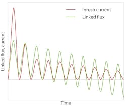
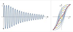
When a transformer is re-energized, an inrush current occurs that can greatly exceed the nominal current. If the transformer core still contains residual magnetism, the first peak current can even reach the level of the short-circuit current. These high currents can cause undesirable effects, such as mechanical deformation of the windings, incorrect triggering of protection equipment, increased stress for the installation, and voltage dips in the grid. Only the ohmic components, such as the winding resistance, are capable of attenuating the high inrush currents to a stable level within just a few cycles (Fig. 1).
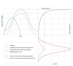
The highest inrush current occurs when the voltage is applied near the zero crossing and the polarity of the voltage is applied in the same direction as the residual magnetism in the core or the corresponding limb (Fig. 2, [Formulas 1-3]). If the core reaches saturation, the transformer's inductance is greatly reduced. The current is now only limited by the winding resistance on the high-voltage side and the impedance of the connected transmission line.
Influence of residual magnetism on electrical routine and diagnostic measurements
The residual magnetism can be as high as 90% of the magnetic flux density (B) during operation. In the event of a fault or during routine tests, various electrical diagnostic techniques can be used for analyzing the condition of a transformer. Residual magnetism influences certain diagnostic measurements in such a way that a reliable and meaningful analysis becomes nearly impossible.
Particularly, when performing exciting current measurements, the magnetic balance test, or sweep frequency response analysis for localization of faults in the core, residual magnetism may have such a negative effect that results become unsolvable.
Influence on exciting current measurements
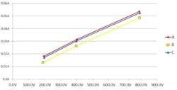
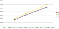
Measuring the exciting current can provide evidence for potential faults in the core. Faults in the core lead to an increasing exciting current. If reference values for the exciting current are available, these can be used for the assessment. Since exciting currents do not have a linear behavior to the applied voltage, measurements for comparison with the reference values must be performed at the same voltage. The assessment is performed based on a typical pattern of a three-limb or five-limb transformer or based on reference measurements if they are available. The magnitude of the magnetization current depends on the length of the magnetized path. This is virtually identical for the windings on the outer limbs, but lower for the winding on the middle limb (Fig. 3). If there is, for example, residual magnetism on the middle limb, this can easily lead to incorrect interpretations and a reliable diagnosis becomes impossible (Fig. 4).
Influence on the magnetic balance test
The magnetic balance test, i.e. a test of the flux ratio, is appropriate as a routine electrical field test and as an additional diagnostic method when a fault is suspected in the core. In the magnetic balance test, AC voltage is applied to a winding and the induced voltage is measured on the two other phases.
This should result in a typical pattern: If, for example, a voltage of 100V is applied to the winding on the middle limb, the measured voltages on the other windings should each display a value of approximately 50V. This can be explained by the two magnetic paths with the same length. When a voltage is applied to one of the windings on the outer limbs, this results in a different pattern, as the magnetic paths have different lengths. If the recorded pattern deviates from the anticipated pattern, this can indicate either problems in the core or can be related to undesirable effects of residual magnetism.
Influence on sweep frequency response analysis measurements
The sweep frequency response analysis (SFRA, or FRA) uses frequency response analyses to describe the dynamic characteristics of an oscillating network based on its input and output signals. The SFRA measurement method is described in IEC 60076-18 and IEEE C57.149-2012 and has become increasingly accepted as a diagnostic method.
A transformer reflects such an oscillating system, consisting of various series and parallel resonances with corresponding inductances (L), capacitances (C) and resistances (R). When one parameter is changed, for example the main inductance due to a core problem or the geometric shift of a winding, one or more characteristic resonance points is/are also displaced or shifted.
Every electrical network has a unique frequency response, its so-called fingerprint. Interpretation of an SFRA measurement is based on a comparison of measurements, for example with the initial fingerprint or with other transformers of the same type. The plot of a fingerprint should not change throughout the entire life cycle of a transformer. All influences which could affect SFRA measurements must therefore be avoided, as they could lead to misinterpretation of the obtained test results.
Since residual magnetism influences the frequency response particularly at lower frequencies, where the magnetization inductance dominates the response, it is vital to ensure that the transformer has been demagnetized before performing the measurement. Meanwhile, because of this pronounced and well understood influence at the lower frequencies, an SFRA measurement is effective in verifying residual magnetism.
The SFRA measurement reflects the main inductance through the first resonance points. Fig. 5 shows the typical resonance points of a three-limb transformer's main inductance. Two significant parallel and series resonance points can clearly be seen on the outer windings. This can be ascribed to the two magnetic paths with different lengths. In comparison with this, the winding on the middle limb displays only one characteristic single resonance point.
As previously explained for the inrush current, the inductance changes depending on the degree of core magnetization, whereby Ldemag > Lmag. A resonance point comprises a network of capacitances and inductances, and can be described using formula 4. The lower the inductance becomes, as reflected by a state of higher residual magnetism, the more the resonance points move toward higher frequencies.
Demagnetization methods
The following three methods are available for demagnetizing magnetic materials:
1. Demagnetization through vibration
2. Demagnetization through heating up to Curie temperature
3. Electrical demagnetization.
Since the first two methods cannot be used for a transformer, the electrical method becomes the sole option. Manufacturers can apply nominal voltage at nominal frequency on transformers. By gradually reducing the voltage, the core is progressively demagnetized (Fig. 6). To demagnetize transformer cores on-site, it is often only possible to use reduced voltage and frequency signals. In many cases, no adjustable voltage source which can provide the nominal voltage of the transformer, instead of that, only a single-phase source can be used.
Demagnetization of single-phase and three-phase transformers can be performed in a similar way. When working on a three-phase transformer, it is important to consider that magnetic coupling takes place between the phases. Therefore, the phase or limb used during the demagnetization procedure is extremely important and deliberately chosen. It also makes sense to use the high-voltage side for demagnetization as there are more turns associated with this winding to generate the magnetic flux. Hence, the total time for demagnetization can be reduced. Experiments have shown that the middle limb is the most suitable for demagnetization with a single-phase source. Thereby, the flux is distributed symmetrically over the two outer limbs. To determine which winding is associated with the middle limb in a delta winding, the transformer's vector group is required.
The art of accurate demagnetization
There are various approaches for electrical demagnetization. One of these is to reduce the voltage resp. the time in predetermined steps. Depending on their type and size, small distribution transformers or large power transformers can have very different hysteresis parameters. The disadvantage of this approach is that it takes a long time to ensure that both types of transformers can be reliably demagnetized using the same procedure.
To counteract this problem, the current can be additionally triggered while the test is still running to start the next hysteresis cycle. However, since the magnetization current increases very rapidly when the transformer core reaches saturation, this process is fairly inaccurate. Various experiments have shown that in particular small transformers become re-magnetized by the final cycle, which leads to high inrush currents in return.
Demagnetization based on the measurement of the magnetic flux has proven as the safest and most efficient approach, as it works reliably with both small and large transformers. However, this approach places very strict measuring requirements on the used equipment, as the voltage needs to be continuously measured over time and the integral has to be derived from this [Formula 5]. It is important to avoid any "secondary hysteresis" during demagnetization. The occurring residual magnetism can lead to an apparent-demagnetization.
Demagnetization measurement procedure
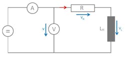
Since the voltage, and thereby also the magnetic flux of the main inductance LH cannot be measured directly, this voltage needs to be calculated (Fig. 7, [Formula 6]). Therefore, the winding resistance R must be measured in advance and the voltage drop of the winding resistance then subtracted from the measured voltage. Formula 7 shows the calculation of the magnetic flux on the main inductance. Thereby фR(0) represents the initial flux, which corresponds to the residual magnetism.
The test set up for demagnetization with OMICRON's testing solution is very simple: In fact, users only require the CP SB1 switchbox and CPC 100 test instrument. Thanks to the switchbox, rewiring is no longer necessary after measuring transformer's ratio or winding resistance. After entering the transformer's vector group and the test current in the "Demag" test card, the CPC 100 initiates the procedure and the residual magnetism is reduced to virtually zero.
The core can be saturated in both directions using the CPC 100. The specific hysteresis parameters per transformer are then determined and the initial flux is calculated. On the basis of these parameters, an iterative algorithm is then used to change both the voltage and the frequency. While this is taking place, the CPC 100 is constantly measuring the flux ф in the core. Using multiple iterations, the core is demagnetized to below 1% of its maximum value. Following the demagnetization procedure, several magnetic domains revert back into their preferred orientation. This procedure is also referred to as magnetic viscosity. The effect can be determined when performing demagnetization once again, although it is actually negligible and therefore is not really important in practice.
The CPC 100 therefore offers a practical and reliable solution to quickly demagnetize small distribution transformers as well as large power transformers. Together with the Primary Test Manager software and the Switchbox the test can be done most convenient.
Example based on a 350 MVA transformer
A 350 MVA-YNyn0 power transformer manufactured in 1971 and rated 400/30kV was tested.
For verification of state purposes, SFRA measurements were conducted using OMICRON's FRAnalyzer. The transformer's condition was recorded immediately after removing it from service with an initial SFRA measurement. Subsequently, a DC winding resistance measurement was carried out on phase B (which was wound on the middle core limb), and another SFRA measurement was then taken. Lastly, the transformer was demagnetized using the previously described method and then checked by performing a final SFRA measurement.
The results after the demagnetization procedure are shown in Table 1:
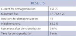
Table 1: Results following demagnetization of the 350 kV transformer
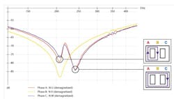
When comparing the SFRA results of the individual phases, it becomes apparent that the transformer displays residual magnetism after being isolated from the power system (Fig. 8). After the demagnetization procedure, all resonance points moved towards lower frequencies as expected, and the typical SFRA pattern of a three-limb transformer can be seen. The transformer can therefore be considered as demagnetized.


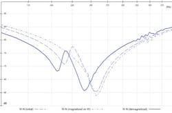
Fig. 8: Phase comparison of the SFRA results with different remanence conditions
Conclusion
This article highlights the importance and the effect of residual magnetism. It should also increase the awareness of the associated risks with re-energizing transformers after an outage.
Within the last few years, the first testing devices (such as OMICRON's CPC 100) have been developed which allow a reliable on-site demagnetization of transformers without any major additional effort. Demagnetized transformer cores minimize the risk for personnel and equipment during installation. The SFRA measurement method is now described in IEC 60076-18 and IEEE C57.149-2012 and has become increasingly accepted as diagnostic method. To gain reliable and reproducible measurement results, we recommend demagnetizing the transformer core before performing SFRA measurements.
Using OMICRON's CPC 100 test instrument together with Primary Test Manager and the CP SB1 switchbox, the test set up for demagnetization is simpleand requires no rewiring. The residual magnetism of transformers can then automatically be reduced almost to zero. This counteracts the effects of high inrush currents and increases the reliability of diagnostic testing.

Literature:
[1] "On the ringdown transient on transformers"
(N. Chiesa, A. Avendano, H. K. Høidalen, B. A. Mork, D. Ishchenko and A. P. Kunze)
[2] "Investigation on the Behavior of the Remanence Level of Protective Current Transformers"
(J. Dickert, R. Luxenburger, P. Schegner)
[3] "Mitigation of Inrush Currents in Network Transformers by Reducing the Residual Flux with an Ultra-Low-Frequency Power"
(Baris Kovan, Francisco de León, Dariusz Czarkowski, Zivan Zabar und Leo Birenbaum)
[4] "Remanent Flux Measurement and Optimal Energization Instant Determination of Power Transformer"
(Goran Petrović, Tomislav Kilić, Stanko Milun)
Formulas: