A New Perspective Leads to Innovation at 765 kV
Time frame, budget, materials and design often are the critical factors governing the success of an electric utility project. Improvements on any one of these four factors make a project much more feasible and enticing for a utility. At Commonwealth Edison Co. (ComEd), an Exelon utility, it often is the case, as voltage increases, each of these factors takes on a new level of difficulty. It is no surprise any work on ComEd’s highest voltage lines of 765 kV bear the utmost level of concern and attention. Even more demanding, the outages at this voltage are limited and it is not easy to find the same materials. All this and more made ComEd’s 2018 Wilton Center project unique in its challenges and, more significantly, its solutions.
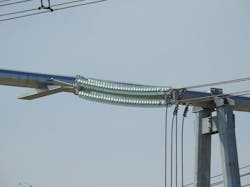
ComEd owns and operates 90 miles (145 km) of 765-kV overhead lines, which were installed in the 1980s and have required relatively little maintenance. All the original lattice tower structures were built to support a quad-bundle conductor (four sub-conductors per phase) design, unique to their voltage class. In 2018, three dead-end assemblies needed to be replaced at ComEd’s Wilton Center substation. This scope introduced installation challenges ComEd had not been faced with in more than 30 years, which led to the development of customized tooling, hardware and a ground assembly jig.
These innovations enabled the utility to complete the project in nearly half the time and at a significant savings compared to a traditional installation. Based on its success, the approach taken on this project will govern the standards and installation methods of 765 kV for ComEd and potentially the industry.
Many Challenges
Most of ComEd’s 765-kV lines terminate in the expansive yard of the Wilton Center substation, located south of Chicago, Illinois, U.S. In 2018, the utility sought to modify the layout of this substation for more effective operation. The project scope included moving a substation termination structure from its original position by 100 ft (30 m) into the existing span, moving it out from the station to make room for new equipment.
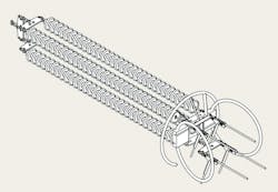
In addition to designing a new structure, the scope also included replacing existing dead-end assemblies for all three phases. Because each phase contained four sub-conductors in a square orientation, with 18-inch (457-mm) spacing center to center, the design and installation were very different from typical 345-kV and 138-kV assemblies. Original conductor was reused to avoid complications with sub-conductor tensioning, because of the limited outage time frame.
The project faced obstacles early in the design phase, as utility engineers determined many materials for the original 1980s dead-end assemblies were obsolete and only available through ComEd’s legacy stock, kept for emergencies. Complicating the problem, specifications governing the assemblies were outdated in most cases. Therefore, all materials had to be verified well before construction could begin.
Installation practices for 765-kV lines historically have been the most significant on ComEd’s system. They require a long construction time frame because of the nature of the quad-bundle assembly and its unique challenges. The obstacles start at the beginning of the traditional installation process when the constructor is required to build the assembly while hanging it suspended vertically. Assembling it on the ground poses problems because of the cubic geometry of the assembly, which also is unique compared to other voltage classes.
Even once assembled successfully, there are additional risks. When the assembly first is connected to the structure, the insulators hang straight down, requiring the utility to tension each sub-conductor separately — which truly is a challenge. As they are tensioned, the long insulator strings, with 32 bells each, tend to droop when pulled up to the final position. During this process, it is inevitable for a pinch point to form in an insulator string. At such a high-stress location, it is possible to bend or crush the insulator pins securing the bells to each other in the ball and socket connection. If insulator pins are compromised, maintenance problems can erupt quickly, which ComEd is dedicated to avoiding.
The unorthodox nature of the 765-kV strain assemblies also adds to the utility’s safety concern during installation, as most construction crews do not have experience or familiarity with the specialty hardware or processes.
Because of all these risks, ComEd’s transmission engineering department worked to innovate on the dead-end concept and apply the utility’s own unique solutions. The first answer to the dead-end assembly challenge was to create an assembly design that not only met the original needs but improved on the design for the future.
After realizing orders could not be placed for original parts, ComEd engineers worked with Burns & McDonnell to identify a manufacturer that could provide an entire dead-end assembly from its facility. Each part included in the assembly had to meet strict guidelines before it was accepted into the design.
First, minor parts had to be standard on the system, making them easily compliant with any existing maintenance programs. Second, each part had to meet ComEd’s strength and materials criteria as defined by its standards, the most challenging of which was the need for the entire assembly to be Charpy V-notch impact-tested for large galloping impacts. Third, ComEd required the vendor to be able to make the assembly a kit and verify all parts fit prior to shipment. The kits would be easy for ComEd to store for emergency supplies and eliminate confusion of missing parts on-site as materials are delivered. Each box delivered would contain one full dead-end assembly.
After finding the appropriate sourcing for the ComEd assembly, the final step was to make a specification clearly showing how the assembly was built and the loading criteria for which it could be used. This specification was the first in the ComEd standards library to use the considerable power of 3-D modeling. After the initial design was completed, it was scrutinized for opportunities to improve installation. The area with the most opportunity was the construction process itself and associated tooling.
As the project design drawings came together, ComEd overhead transmission field personnel were invited to comment on the constructability of the project. Having only done select maintenance projects on ComEd’s very reliable 765-kV lines and no major build-outs, this project was the first of its kind for several field personnel. Focusing on safety, senior field members and engineers committed to develop tooling and procedures to execute the uncommon scope using means and methods seen on more typical everyday work.
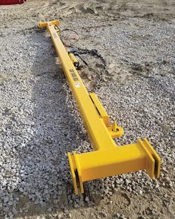
The first tool envisioned was based on the conventional spreader bar, commonly used to install dual-string insulators held together at each end with yoke plates. Because they are used oftentimes on 138-kV and 345-kV systems, the spreader bars are available commercially. Unfortunately, while the spreader bar idea was derived from existing tooling, this is where the similarities ended. Unique design challenges included the quad-bundle design, the spreader dimensions and capacities, and the absence of a commercially available unit.
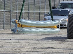
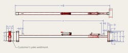
ComEd’s transmission engineers developed a concept that would function as a normal spreader bar, accepting the quad-bundle yokes, spanning approximately 17 ft (5.2 m) and withstanding the full compressive force needed to prevent insulators from drooping. Another design feature included the use of a linear hydraulic unit with an in-line hand pump, where the lever could be pumped without interfering with the insulators as other ratcheting-type extenders would in a quad-bundle design.
The bar was designed for use beyond this single project, so various extended dimensions were a requirement. The design also incorporated a feature that would enable field personnel to make macro dimension adjustments before making the final micro adjustment with the finite-length hydraulic unit. Lifting points also were integrated into the design for ease of use. ComEd worked with Alloy Sling Chains Inc. to model fully and build the final design.
After developing the workable spreader bar, the engineers set out to provide a way of assembling the complete quad-bundle insulator assembly on the ground. This goal was driven from multiple angles, including reducing the potential damage to the insulators, making it easier and safer to construct, and providing a platform to mesh with the spreader bar. A template, in the form of a jig, was developed by the engineers that accomplished these goals.
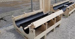
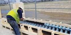
The insulator jig was designed preliminarily using common, easy-to-work-with materials such as a wood frame and smooth-wall plastic drainpipe. Wood was used on this first iteration to validate the new concept prior to rolling out a long-lasting aluminum unit. The smooth-wall plastic drainpipe was used not only because of its dimension convenience but also to accommodate more handling-sensitive insulators, such as room-temperature-vulcanizing (RTV) coated glass. While the complete jig was made specifically for quad-bundled 765 kV, it was designed modularly to accommodate 18-inch dual or quad configurations down to 138 kV. This was done by splitting the unit into multiple pieces and using removable inserts for the second level of insulators. The units included built-in forklift positions, so they could be handled easily anywhere with fork-capable equipment. ComEd worked with Wisconsin Built Inc. to construct the jig.
Successful Implementation
With all the necessary components delivered and innovations prepped for their first-ever use, the overhead portion of the 765-kV work started in the summer of 2018. Once the substation structure was erected, ComEd overhead crews initiated their work. In preparation for the installation, the crews removed the existing strain assemblies and tied the three phases (12 conductors) off to the new structure to avoid contact with the ground. This also prevented the need to remove all existing spacers in the span.
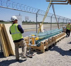
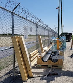
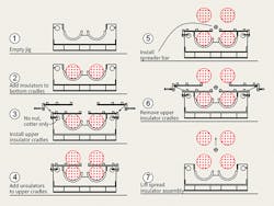
The next step was to implement the jig design, enabling assembly of the specialized dead ends on the ground. Shortly after the assembly was connected, the second unique piece of tooling was used. The newly invented quad-bundle hydraulic spreader bar was connected to a lifting device and lowered into the cradle assembly. ComEd crews then hydraulically extended the spreader bar using the hand pump, so the insulator strings were put under tension and the board supporting the top two insulators strings could be removed from the jig. This enabled the entire assembly, with the spreader bar, to be lifted into the air.
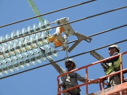
Once in the air, suspended from two lifting vangs included in the spreader bar design, the assembly was brought up to the existing connections on the new termination structure and secured while being held horizontally. The true value of the ComEd design quickly became apparent when the installation crews were able to connect and tension all four sub-conductors simultaneously, something that had not been possible with previous designs. The final step was the shortest to complete—contracting the hydraulic spreader bar and removing it from the now-airborne assembly for use on the next dead end.
The planned construction time for the overhead portion of the project was cut by more than half because of the effective and unique solutions developed by ComEd’s engineering and construction teams. With such an effective means to construct the assemblies proven, ComEd now is pursuing standardization for any future projects with a similar scope. Beyond the construction methods themselves, it is important to note the kitted delivery of the 765-kV assemblies reduced the time spent looking for materials and can be attributed to the time savings.
The impressive results achieved by these innovative efforts clearly show the value of looking at existing industry practices from new perspectives. By the end of the project, the more traditional spreader bar and jig had been applied in a new way, enabling the use of common means and methods to perform uncommon work safely. Revisions are under way to expand the design to accommodate different spacings, such as 24 inches (610 mm) and others being considered.
For more information:
ComEd | www.comed.com
Alloy Sling Chains | https://ascindustries.com
Burns & McDonnell | www.burnsmcd.com
Wisconsin Built | www.wisconsin-built.com
About the Author
Tyler.Petersen
Tyler Petersen is a senior engineer experienced with transmission overhead maintenance at Commonwealth Edison Co. (ComEd) in Chicago, Illinois, U.S. He coordinates the analysis, design, and planning of routine and emergent maintenance activities on ComEd’s nearly 5400 miles (8690 km) of overhead transmission lines from 69 kV to 765 kV. Petersen also has experience in upgrading older construction with new equipment on both wood and steel structures. He holds a BSEE degree and a master’s degree in engineering management, both from Valparaiso University.
Ryan Cisko
Ryan Cisko is a professional engineer experienced with overhead and underground transmission design at ComEd. His overhead experience includes wood and steel structure design, North American Electric Reliability Corp. facilities ratings, specifications development and emergent event response. Cisko’s background lies in mechanical and aerospace engineering in which he holds dual degrees from the Illinois Institute of Technology at Chicago.
