Cybersecurity Boundary Protection for Transmission Facilities - Part One
This three-part series discusses the requirements and cybersecurity architecture and controls associated with protecting the network boundary for transmission facilities. Most of these cybersecurity controls are commonly deployed but boundary protection is still the leading issue identified by the National Cybersecurity and Communications Integration Center’s (NCCIC) Industrial Control Systems Cyber Emergency Readiness Team (ICS-CERT). The series explores why boundary protection is difficult to perform correctly and consistently, as well as areas to check when assessing a boundary protection system. Several examples of boundary protection devices and configurations are presented, analyzed and updated to address issues. Part One addresses the first of the six indicators outlined in the ICS Cert report: inadequate boundary protection for industrial control system (ICS) networks. The series was presented at the CIGRE US National Committee 2018 Grid of the Future Symposium.
One of the fundamental security controls for electric power transmission facilities is the design and deployment of boundary protection. The North American Electric Reliability Corporation (NERC) Critical Infrastructure Protection (CIP) Standard for defining an Electronic Security Perimeter (ESP) is detailed in NERC CIP-005-5. This requirement applies to transmission facilities with High or Medium Impact Bulk Electric System (BES) Cyber Systems and their associated Protected Cyber Assets with routable protocol connectivity.
In the Guidelines and Technical Basis for NERC CIP-005-5, NERC provides the functions for an ESP:
- Defines a zone of protection around the BES Cyber System.
- Provides clarity for entities to determine what systems or Cyber Assets are in scope and what requirements they must meet.
- Defines the scope of Associated Protected Cyber Assets that must also meet certain CIP requirements.
- Defines the boundary in which all Cyber Assets must meet the requirements of the highest impact BES Cyber System that is in the zone (the high-water mark).
Secure network design has many historical references to defining a boundary. In 1994, Bellovin and Cheswick defined security domains as a set of machines under common administrative control, with a common security policy and security level. That definition still holds true today.
With lots of history and millions of boundary protection devices installed worldwide, why is boundary protection the leading issue identified by NCCIC’s ICS-CERT when performing assessments? There are some indicators in the FY 2016 report:
- Inadequate boundary protection for ICS networks.
- No logical separation of the ICS from enterprise networks or untrusted networks (such as the internet).
- No dedicated jump server to provide access to ICS data.
- Using the same user authentication credentials for the jump server and the enterprise network.
- Too many communication flows (ports and services) allowed to the boundary devices.
- Inadequate security services available in the demilitarized zone (DMZ) to support ICS system patching and updates.
Here we explore the first indicator and what steps should be taken to mitigate the associated risk. Part Two will explore two other indicators.
Inadequate boundary protection
The first indicator demonstrates that in many cases, the boundary protection is not configured properly and allows too much access from other security domains such as the enterprise network, and potentially internet-connected devices.
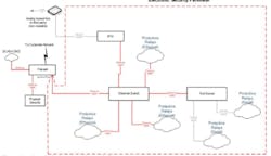
The first area to review is the number, location and type of access points that exist on the substation network. This access point configuration is dependent on the types of communication and protocols as well as operational requirements. For example, transmission facilities often have a primary and secondary communications paths for SCADA information and in some cases, they may have to provide third-party access to a subset of data points. A simple example of this potential configuration is shown in Figure 1.
In this example, we have two potential access points identified — the firewall Ethernet port and the serial port on the Remote Terminal Unit (RTU). There are several areas where additional information is required to determine the true level of risk from this configuration:
- Firewall configuration
- Modem and RTU configuration
- Physical access
The firewall requires proper configuration to protect the substation network from unauthorized access. The firewall should be configured to only allow access from a limited number of pre-defined devices from the corporate network; ideally only from a jump server that provides additional authentication and encryption of remote access traffic.
Ensure that all firewall changes are reviewed and approved through a configuration management process. The failure to track all changes to a system is a major factor in security systems becoming less effective over time.
The firewall should also only allow the required network ports and services to perform the operational requirements of the substation. For example, if there is no operational requirement to allow HTTP or HTTPS access to the equipment on the substation network, then those services should be blocked by the firewall configuration.
Firewalls themselves often require communication between a management console and the individual firewall devices at remote locations. It’s important to understand what services are required between firewall devices for operation and confirm that those services are required. Firewalls may have a separate set of implied rules that are enabled by default and are not normally displayed on a management console view of the active firewall rules or on an operator’s console. Review your firewall configuration carefully for terms such as:
- Accept control connections
- Accept update connections
- Accept dynamic routing updates
- Accept Domain Name Service
- Accept Web connections for firewall administration
A comprehensive understanding of the management architecture of the firewall systems is essential in maintaining a secure configuration across all access points. Some firewalls have global parameters that are applied to all devices under management by a specific console or instance, while other implementations define parameters that require customization for each individual device or software feature enabled. The configuration management process provides a check and balance to ensure that firewall devices remain configured properly.
Verify that your firewall design and maintenance processes actually require all the enabled services and disable any services not required.
The modem and RTU configuration should require authentication to establish the dial-up connection. While the connection may appear to be only SCADA data, the configuration on the RTU should be reviewed to determine if remote access is possible from the dial-up connection. Some RTU and serial protocols allow both data and control commands to be carried at the same time.
Finally, physical access controls to the substation and control network are a major security design requirement — otherwise a knowledgeable attacker can quickly access many of the devices or install their own remote access device to exploit the network later from a safe distance.
Part Two will discuss two more of the six total indicators outlined in the ICS Cert report and what steps should be taken to mitigate the associated risk:
- No logical separation of the ICS from enterprise networks or untrusted networks (such as the Internet).
- No dedicated jump server to provide access to ICS data.
About the Author
Jeff Pack
Jeff Pack specializes in cybersecurity services for POWER Engineers, Inc. He has over 31 years of experience in electric utilities, energy research and development, and information security solutions. He is an experienced leader and subject matter expert in the cybersecurity field, including program development, consulting, and operations. Jeff has also provided executive and team leadership for numerous projects related to cybersecurity and operations. He has bachelor’s degrees in engineering and computer science from Montana Tech and an MBA from Boise State University.

