A Novel Approach to Sub-transmission Islanding Protection: Extending DGP Technology to 69kV Systems
Key Highlights
- Unintentional islanding poses safety risks and equipment damage, necessitating rapid detection and disconnection of DERs from the grid.
- Traditional detection methods like inverter-based detection and Direct Transfer Trip (DTT) have limitations in reliability, cost, and infrastructure requirements.
- DGP utilizes power lines as communication channels, employing advanced coupling and digital signal regeneration to ensure high reliability over long distances and high voltages.
- The innovative use of existing CCVTs as coupling devices enables extension of DGP technology to 69kV systems without significant hardware modifications.
- Field tests confirm DGP’s capability to operate reliably over 25 miles, with potential reach up to 50 miles, providing a scalable, cost-effective solution for modern grid protection.
The increasing integration of Distributed Energy Resources (DER) into our electrical grids brings a host of benefits, from enhanced energy security to reduced carbon emissions. However, it also introduces new technical challenges, such as the phenomenon of unintentional islanding, which occurs when a portion of the grid containing DER becomes electrically isolated from the main utility grid but remains energized by the DER. This can lead to unsafe operating conditions, with voltage and frequency deviations that can damage equipment and pose a risk to utility personnel working to repair the island. To address this, the IEEE 1547-2018 DER interconnection standard mandates that unintentional islands be detected and DER disconnected from the grid within two seconds.
A novel solution for islanding protection in sub-transmission systems extends Distributed Generation Permissive (DGP) technology from medium-voltage distribution to 69kV sub-transmission. The approach enables faster, safer, and more cost-effective DER interconnection.
Existing Islanding Protection Methods and Their Limitations
Several methods are currently employed to detect and mitigate unintentional islanding. The most common approach relies on DER’s own inverter to locally detect the islanding condition and cease power generation. While simple and widely used, this method is not always reliable. It is susceptible to what are known as Non-Detection Zones (NDZs), where the local detection algorithms fail to recognize the island, particularly in scenarios with multiple DER types or a close match between local generation and load.
For situations where local detection is deemed insufficient, utilities often turn to Direct Transfer Trip (DTT) systems. DTT uses a dedicated communication channel, such as fiber optic cables, to send a trip signal from a protective device at the substation to the DER’s disconnection point. While highly reliable, DTT can be expensive and time-consuming to implement, especially when new communication infrastructure needs to be built.
A New Paradigm: Distributed Generation Permissive
A promising alternative to these traditional methods is the Distributed Generation Permissive (DGP) system, a form of Powerline Conducted Permissive (PLCP) signal. The DGP approach, as described in a 2018 IEEE paper by Sadan and Renz, utilizes the power lines themselves as the communication medium. A transmitter at the substation continuously sends a permissive signal to receivers at each DER’s point of common coupling (PCC). If the connection to the main grid is lost, the permissive signal is interrupted and the receiver at the DER initiates a trip, which disconnects the DER from the islanded section of the grid.
This permissive signal approach is inherently fail-safe — any interruption, whether from an actual islanding event or a deliberate command from the utility, results in the disconnection of the DER. It provides high dependability with a low probability of false trips.
The Technology Behind DGP
The effectiveness of the DGP system stems from several innovative technological advancements that distinguish it from older Power Line Carrier (PLC) systems. These innovations address the challenges of signal integrity, noise and distance in the harsh electrical environment of power distribution lines.
Advanced Coupling and Signal Transmission
At the heart of the system is the method used to inject and receive the high-frequency permissive signal onto the power lines. For medium-voltage applications, DGP employs a specially designed capacitive coupler that acts as a high-pass filter, allowing the 50-500 kHz DGP signal to pass while blocking the 60 Hz power frequency.
A key innovation, protected by U.S. patents, is the use of differential coupling. Instead of using a single phase and a ground return, the DGP system injects the signal across two of the three power phases. This technique provides significant common-mode noise rejection, dramatically improving the signal-to-noise ratio (SNR) and overall system reliability. It also allows the system to function effectively on ungrounded delta systems, which are common on sub-transmission utility networks.
Signal Regeneration for Extended Reach
To overcome signal degradation over long distances, DGP employs a sophisticated digital technique called signal regeneration. Unlike traditional analog systems that use simple amplifiers (repeaters) DGP uses a combination of Frequency Division Multiplexing (FDM) and Time Division Multiplexing (TDM) to regenerate the signal. This allows for multiple DGP signals to coexist on the same line at different frequencies and time slots. A regenerator unit receives a weakened signal on one frequency, decodes the digital message and then re-transmits a fresh, full-strength signal on a different frequency and time slot. This process effectively boosts the signal without accumulating noise, enabling the system to cover extensive circuit lengths and overcome signal loss caused by capacitor banks and other inline grid equipment.
|
Feature |
Legacy Power Line Carrier (PLC) |
Distributed Generation Permissive (DGP) |
|
Physical Medium |
High Voltage Transmission Lines |
Medium Voltage Distribution Lines |
|
Signal Type |
Analog Audio Tone |
Digitally Encoded Messages |
|
Signaling Technology |
Narrowband FSK |
Wideband Modulation |
|
Frequency Blocking |
Required (Wave/Line Traps) |
Not Required (Digital Frequency Separation) |
|
Coupling Method |
1-Phase (CC or CCVT) |
2-Phase Differential (Capacitive Coupler) |
|
Output Power |
~10W |
~0.1W |
|
Regeneration |
No (Single Frequency Operation) |
Yes (FDM/TDM for Extended Reach) |
Table 1: A comparison highlighting the key differences between legacy PLC and modern DGP technology.
The Next Frontier: Extending DGP to 69kV Sub-transmission
While DGP has proven its value on medium-voltage distribution systems, applying it to higher-voltage sub-transmission lines presented a new set of challenges. These include:
- Higher Voltage: The standard 36kV DGP coupler is not rated for 69kV operation.
- Increased Noise: Higher voltage lines typically exhibit higher levels of electrical noise.
- Longer Distances: Sub-transmission lines often span much greater distances than distribution feeders.
- Networked Topologies: Sub-transmission systems are frequently networked and fed from multiple sources, unlike the typically radial structure of distribution circuits.
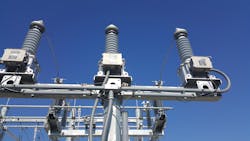
The research team at GridEdge hypothesized that a standard Coupling Capacitor Voltage Transformer (CCVT), a device already common in high-voltage substations for voltage measurement and traditional PLC applications, could be used as a coupling device for the DGP signal. The first step was to measure the transfer function of a 69kV CCVT. The results were highly encouraging, showing that the CCVT had a compatible frequency response and even a slightly lower insertion loss (1-2 dB) compared to the standard 36kV DGP coupler (3-4 dB).
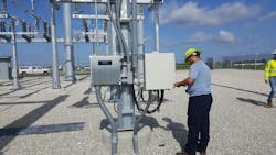
Following successful lab-based tests on de-energized equipment, the system was tested on energized 69kV lines at a utility test center. These tests confirmed that the DGP modem and its associated circuitry could operate reliably in a high-voltage environment, recovering within seconds after line switching events. A critical lesson learned during this phase was the importance of proper grounding to prevent parasitic signal paths that could degrade performance.
Real-world Deployment and Success
With the proof-of-concept validated, the DGP system was deployed in a real-world utility application on a networked 69kV sub-transmission line. The project involved a DER site located between two transmission stations — approximately 25 miles from one end and 19 miles from the other. To accommodate the networked configuration, a DGP transmitter was installed at each of the two source substations and a single DGP receiver was installed at the DER site.
The protection scheme was designed so that the receiver would only initiate a trip if it lost the permissive signals from both transmitters, a logic that was successfully tested in the lab prior to deployment. During commissioning, a series of trip tests were performed with 100% success. The system demonstrated reliable communication over the 25-mile distance using only 60% of the transmitter’s maximum output power, suggesting that a reach of up to 50 miles is feasible.
The system’s design also inherently handles line faults correctly. For a temporary fault that causes a brief breaker operation and reclose, the signal is lost for less than a second and is re-established before the two-second trip timer expires, preventing a nuisance trip. For a permanent fault, the protection relays at the substation will open the breaker and de-energize the line, which also stops the DGP signal, leading to the desired disconnection of the DER.
A Cost-effective Path Forward
The successful extension of DGP technology to 69kV sub-transmission systems marks a significant advancement in grid protection. By leveraging existing, industry-standard CCVTs as coupling devices, the system simplifies engineering and reduces the need for specialized equipment. This approach provides a highly reliable, fail-safe and cost-effective alternative to the expensive and time-consuming installation of dedicated fiber optic lines for DTT.
GridEdge and its manufacturing partner, Custom Electronics Inc. (CEI) offer a 69kV Distributed Generation Permissive (DGP) solution that enables safer, more cost-effective integration of DER into utility grids. The new system addresses this critical safety challenge: protecting utility workers and equipment when distributed energy resources are disconnected from the grid and form an unintentional island that may cause dangerous power fluctuation.
As more large-scale renewable energy projects seek to interconnect at the sub-transmission level, solutions like the DGP system are crucial for accelerating their deployment. By providing a secure and dependable method for islanding protection, this technology helps ensure the stability and safety of the grid while paving the way for a cleaner energy future.