Point-to-Point Digital Secondary System Design for a Transmission Substation
In recent years, Duke Energy has increased the use of fiber optics in alarming and communication schemes, with more limited use in protection and control. However, copper has traditionally been used to connect current transformers (CTs) and potential transformers (PTs) to protective relays and metering devices.
A modern substation employing a digital secondary system (DSS) uses fiber-optic cables to communicate between intelligent electronic devices (IED) in the control house and merging units (MUs) in the switchyard. This solution eliminates copper cables between the primary equipment and the protective relays, replacing them with a few fiber-optic connections, potentially leading to lower substation construction costs and reduced construction time.
The point‑to‑point digital secondary system (P2P DSS) uses a simple architecture in which an MU is directly connected to an IED using a fiber-optic cable. Duke Energy’s initial focus has been on evaluating designs that use a point-to-point (P2P) approach to obtain the benefits of reducing the use of copper while eliminating the need for additional network devices, like network switches and clocks. This approach requires fewer components, minimizes the need for additional knowledge and skills required for a switched network, and minimizes changes required to existing setting templates/designs.
Part 1 of this series describes a P2P DSS design for an existing 100 kV transmission substation at Duke Energy, using P2P IEDs and MUs available from an IED manufacturer, the P2P DSS is designed for the entire substation. Following the P2P DSS design, Part 2 will compare the protection scheme unavailability between the traditional substation and the P2P DSS design using fault tree analysis. Also discussed are test results from the actual protection and control (P&C) devices that compare the protection system operation speed between the traditional system and P2P DSS.
The P2P MU and the protection IEDs used for this study have four and eight communication ports, respectively. This port limitation poses a unique challenge when implementing bus differential protection for 10 breakers. Similarly, supplying bus voltages to 18 IEDs requires multiple MUs connected to the same PT. Solutions for these problems are described in detail in the article. In summary, this article provides a detailed P2P DSS design for an existing transmission substation at Duke Energy. Similarly, it includes quantitative data on total device count, protection scheme unavailability, and protection system operation speed of two secondary systems. The technical data will assist Duke Energy with the decision-making process regarding the evaluation of a P2P DSS for their system.
Duke Energy’s Transmission Substation
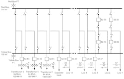
The transmission substation used in this study consists of six pairs of double-circuit 100 kV network-sourced transmission lines for a total of 12 individual line terminals, two bus lines sourced independently from 230/100/44 kV auto banks at an adjacent station, three 100/44 kV power transformers, and two 100 kV capacitors on a breaker. Fig. 1 shows the single-line diagram of the transmission substation used for the case study. The normal configuration for the station includes half of the network double-circuit lines tied to the Red Bus and half tied to the Yellow Bus. All breakers run normally closed.
P2P DSS Design
Since the substation is large, the design is broken down into multiple subsystems based on the configuration used for protecting a network element. For each subsystem, the secondary system and its associated P&C devices for the existing traditional substation are presented first. Next, the P2P DSS design for the same subsystem is described. When developing the P2P design, full redundancy of P&C devices is considered.
Similarly, the existing protection philosophy and operation methodology are maintained in the new P2P design. Although the P2P DSS design is carried out for the complete substation, for brevity, only double-bus double-breaker, bus differential, and bus PT configuration are discussed.
Double-Bus Double-Breaker Configuration
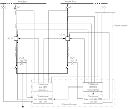
As shown in the substation single-line diagram, Line 1 is connected to the Red and Yellow Buses via two breakers. Fig. 2 shows the secondary connection between primary equipment, circuit breakers (CBs), CTs, PTs, and capacitor voltage transformers (CVTs), and protection IEDs for Line 1. Separate CTs, PTs, and CVTs are installed to aid the design of redundant protection systems. Two-line IEDs, primary and secondary, provide redundant line current differential protection to Line 1. For each breaker, a separate bay controller IED is installed.
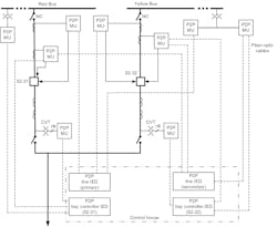
P2P DSS design for Line 1 protection is shown in Fig. 3. To maintain independence between primary and secondary protection, separate P2P MUs and line IEDs are used for each system. The P2P MUs connected to the CTs provide three‑phase current measurements to line IEDs and bay controller IEDs. In traditional design, the Yellow Bus provides bus voltage to both line IEDs and the second bay controller IED (52-32). Two separate MUs provide bus voltage to primary and secondary line IEDs in P2P DSS design. For Line 1 protection, nine P2P MUs and four P2P IEDs are required.
The substation single-line diagram shows ten breakers connected to each bus. Fig. 4 depicts the secondary connection and IEDs for the Red Bus primary bus differential protection. The Red Bus secondary bus differential protection is identical to the one shown in the figure and uses the second set of CTs associated with each breaker (connection not shown). An electromechanical high-impedance differential IED is used for bus differential protection for each phase. Phase A currents from all ten breakers are physically summed before connecting them to the Phase A high-impedance differential IED. A similar connection is made between Phase B and Phase C currents and the remaining differential IEDs as shown in the figure. For an in-zone fault, the differential IEDs command a separate auxiliary relay to trip all ten breakers connected to the Red Bus. Similarly, for Yellow Bus differential protection, three high‑impedance differential IEDs are used for the primary system, and three additional high-impedance differential IEDs are used for the secondary system.
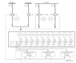
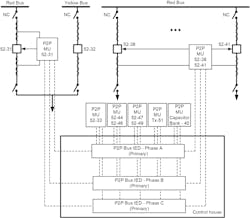
Fig. 5 shows the overall P2P DSS design for the Red Bus primary differential protection. Each bus IED acquires currents from 10 breaker terminals via seven MUs. Overall, the P2P DSS design uses seven MUs and three Bus IEDs for the Red Bus primary protection. For the Red Bus secondary protection, separate MUs connected to the second set of CTs and bus IEDs are connected like the one shown in REF _Ref111645082 \h \* MERGEFORMAT Fig. 5. A total of 28 MUs and 12 Bus IEDs are used for both primary and secondary protection for the Red and Yellow Buses.
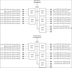
In the transmission substation, 18 IEDs receive three-phase bus voltage from the Red Bus. Similarly, another 18 IEDs receive separate three-phase bus voltage from the Yellow Bus. For a traditional secondary system, this is not a concern. The voltage terminals of all 18 IEDs are connected in parallel with the bus PT secondary circuit. Sharing bus voltage to a large number of IEDs requires multiple P2P MUs in P2P DSS, as the number of communications ports on an MU is limited to four. Fig. 6 shows the P2P DSS design for sharing Red and Yellow Bus voltage to IEDs. Five MUs are needed to share the Red Bus voltage to 18 IEDs.
Similarly, another five MUs provide the Yellow Bus voltage to the other 18 IEDs. Within each bus, separate MUs provide bus voltage to primary and secondary protection IEDs. This design ensures that the loss of an MU does not disable both primary and secondary protection for a particular network element.
Stephen B. Ladd received his BSEE from Grove City College in 1986, MSEE from Georgia Tech in 1987, and MBA from Queens University of Charlotte in 2003. He has been a member of IEEE for 37 years and a member of IEEE-PES since 1987. He is a registered Professional Engineer in the state of North Carolina and has worked at Duke Power, Duke Engineering & Services, and Duke Energy Corporation since 1987. Mr. Ladd has held engineering positions in Substation Apparatus, Protection & Control, and Asset Management. He is currently a Principal Engineer in the Transmission System Standards group.
Arun Shrestha received his BSEE from the Institute of Engineering, Tribhuvan University, Nepal, in 2005, and his MS and PhD in electrical engineering from the University of North Carolina at Charlotte in 2009 and 2016, respectively. He joined Schweitzer Engineering Laboratories, Inc. (SEL) in 2011 as an associate power engineer in research and development. He is presently working as a senior engineer. His research areas of interest include power system protection and control design, real-time power system modeling and simulation, wide-area protection and control, power system stability, and digital substations. He is a senior member of IEEE and is a registered Professional Engineer. He is a member of IEEE PSRC and a U.S. representative of IEC 61850 TC 57 WG 10.
About the Author
Stephen B. Ladd
Stephen B. Ladd received his BSEE from Grove City College in 1986, MSEE from Georgia Tech in 1987, and MBA from Queens University of Charlotte in 2003. He has been a member of IEEE for 37 years and a member of IEEE-PES since 1987. He is a registered Professional Engineer in the state of North Carolina and has worked at Duke Power, Duke Engineering & Services, and Duke Energy Corporation since 1987. Mr. Ladd has held engineering positions in Substation Apparatus, Protection & Control, and Asset Management. He is currently a Principal Engineer in the Transmission System Standards group.
Arun Shrestha
Arun Shrestha received his BSEE from the Institute of Engineering, Tribhuvan University, Nepal, in 2005, and his MS and PhD in electrical engineering from the University of North Carolina at Charlotte in 2009 and 2016, respectively. He joined Schweitzer Engineering Laboratories, Inc. (SEL) in 2011 as an associate power engineer in research and development. He is presently working as a senior engineer. His research areas of interest include power system protection and control design, real-time power system modeling and simulation, wide-area protection and control, power system stability, and digital substations. He is a senior member of IEEE and is a registered Professional Engineer. He is a member of IEEE PSRC and a U.S. representative of IEC 61850 TC 57 WG 10.