High-Voltage Transformer Bushing Assessment Is Critical
Why is understanding high-voltage oil-filled transformer bushings so critical?
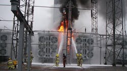
High-voltage power transformers are an essential component of our nation's electric grid infrastructure. Bushings are the most critical component of a power transformer. The voltage gradient between the ground flange and the high-voltage center conductor is much larger compared with the voltage gradients inside the transformer or external lines coming into the transformer. In most cases, if the bushing fails catastrophically, the transformer will have to be replaced or untanked to clean up the failed bushing debris. The cost of large power transformers ranges from a few hundred thousand to over US$5 million with lead times varying from a few months to over a year.
Basics of oil-filled high-voltage bushings
Bushings are interface components so that electrical energy passes through a barrier. The center core is usually made of aluminum or copper which is properly sized to carry the current from one side of the barrier to the other. The center core is contained in an insulation system that is covered with an insulator. Bushing insulation systems of 26 kV and below can be designed using a solid material such as porcelain, silicon, or resin composite. Bushings rated greater than 26 kV need layers of conductive material or foils interspersed with layers of paper to distribute voltage stresses and to minimize large voltage gradients. The layers of conductors and insulation form concentric capacitors between the barrier and center core. Refer to Fig. 1 below.
Today, oil impregnated paper bushings are the most widely used types of bushing for voltages greater than 26 kV. In this design, the paper provides the skeleton to hold the insulating oil. The oil functions as the main insulation and coolant for the bushing. The outer shell is typically porcelain but some manufactures have designs using other material because of long lead times and difficulty in manufacturing of the outer porcelain shells.
Moisture is an enemy to bushing
Moisture is a bushing's worst enemy. As a bushing ages, gaskets lose their ability to seal, thereby paving the most common way for moisture to enter the bushing. If moisture is allowed to enter the bushing, it will start to break down the oil and paper insulation system. This breakdown forms various polar compounds and acids that attack the paper. As the paper breaks down, more contamination is formed. At some point two or more conductive layers will break down and short together. When this happens, the remaining concentric capacitors will have a larger voltage stress across each capacitor. As the breakdown goes unchecked and moisture continues to enter the bushing, the rate at which contamination is being generated inside the bushing increases. This causes other layers to fail. At some point, there is a catastrophic failure of the bushing. Risk increases dramatically with age and voltage level. Bushings rated greater than 230 kV and older than 25 years fall into the highest-risk category. The next lower-risk category comprises bushings rated between 100 kV to 230 kV and older than 35 years.
Although moisture ingress is the leading cause of bushing failures, the good news is there are ways to evaluate the deterioration of a bushing's insulation system. Power factor testing is the industry's standard method for tracking and trending bushing health. Infrared (IR) and visual inspections can be used to track health while the transformer is online. Bushing oil sampling can be used on suspect bushing or bushings in the high-risk category.
Checking bushing health using power factor
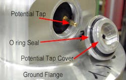
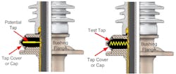
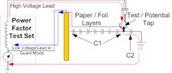
A bushing is divided into two parts. The innermost insulation system is made up of several concentric capacitors, commonly referred to as C1. The outermost insulation system has only a few layers and is referred to as C2. The main purpose of this division is to allow a test connection point for off-line electrical tests. Normally C2 is shorted out by the cap cover when the bushing is in operation. Refer to Fig. 2 below. In rare cases, for bushings rated 69 kV or greater, this point is used to feed a potential device. This is possible because C1 and C2 are not influenced by external factors such as the bushing turret or tank walls. In other words, a bushing can be used as a reasonably accurate capacitor divider to feed a potential device for measuring the voltage that is being applied to the bushing. On bushings that allow for an external potential, the tap is referred to as a potential tap. The potential tap can be easily spotted because it is a stud type connection opposed to a spring. See Fig. 3 below. In either case, a potential tap or test tap can be used for off-line power factor testing.
To setup a transformer bushing for testing, only remove the bushing cap on the bushing under test. Use a piece of wire to tie all high side bushings together and tie all low side bushings together. For a three-winding transformer, tie the tertiary bushings together. Bare 12-gauge wire works great. This reduces interference that can lead to erroneous test results.
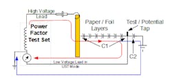
The main core insulation C1 is tested using the Ungrounded Specimen Test (UST) mode, as seen in Fig. 4 below. The current travels out the high-voltage lead to the tap. Here the current splits. But only the current that travels through the C1 capacitor returns to the test source through the meter. Therefore, only C1 is measured in this mode.
The power factor test set calculates the power factor and capacitance value for each test which allows more insight into the health of the bushing. The power factor indicates the amount of contamination while the capacitance value indicates the physical changes in the conductive layers. Increase in power factor indicates the amount of contamination and increase in capacitance indicates if any layers have been shorted out since the last test. The capacitance values reported by the power factor test set are often overlooked but they are the main indicators of a physical change inside the bushing.
The outer layers of the bushing insulation referred to as C2 is tested in guard mode as seen in Fig. 5. The current travels out the high-voltage lead to the tap. Here the current splits. But only the current that travels through the C2 capacitor returns to the test source through the meter. Therefore, only C2 is measured in this test setup.
Checking bushing health using visual and IR techniques
Low oil level is a key indicator that a bushing is leaking oil. If oil is coming out then moisture is getting in. Although power factor testing is one tool in the tool box, they are only performed every few years. Visual inspections, which are sometimes referred to as rounds, are often used to spot signs of an oil leak or notice a large change in oil level from the site glass or oil level gauge. It is not just spotting something but also being aware of how to follow up with an action.
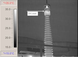
This point leads to performing an IR scan. Because of the losses in a transformer when it is energized and carrying load, the oil is hotter that its surroundings. The heat thermally conducts from the transformer to the bushing which allows a temperature gradient that can be seen using an IR camera. Fig. 6 shows a transformer bushing with normal oil level.
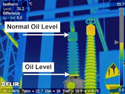
The IR image in Fig. 7 shows the bushing on the right to be full of oil. This is indicated by the heat traveling from the warm transformer tank full of oil up the bushing all the way to the top. The scale on the far right shows the brighter yellow (lighter shade in black and white) having a temperature somewhere around 31°C and the bushing on the left is blue/green (darker shade in black and white) having a much cooler temperature. The lower temperature is because of the lack of oil that allows for good thermal heat flow. Only the very lowest part of the bushing on the left shows any signs of heat being conducted, thus marking the location of the oil level. This was verified by Tennessee Valley Authority's (TVA) Power Service Shop during tear-down of the bushing.
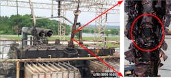
Remember refilling a bushing after it has been found to be lower than the top metal bushing head is not advised. Once the oil drops below this point, the paper layers will no longer be covered with oil. Partial discharge will start and eat the paper like termites while the bushing is energized. See the right side of Fig. 8, where partial discharge ate through the insulation. The damage is irreversible. This will start to be evident in the power factor test but if oil is added before the power factor test, the results will be masked. Refer to Fig. 8 to see the catastrophic results of refilling and then testing after finding a bushing low on oil. The evidence brought to light this fact while performing a root cause analysis.
Checking bushing health using bushing oil sampling
The most invasive test is to pull oil from the bushing and send the sample to a lab for analysis. This is only recommended for the highest-risk category of bushings. As stated earlier, the highest-risk category comprises bushings rated greater than 230 kV and older than 25 years. The second highest category comprises bushings rated 100 kV to 230 kV and older than 35 years.
Recommended tests are as follows (oil sample size needed — two 50-cc syringes):
- Oil Quality Analysis
- Moisture
- Interfacial Tension (IFT)
- Color
- PCB
- Dissolved Gas-in-Oil Analysis (DGA)
- Carbon monoxide, carbon dioxide
- Hydrogen, methane, ethane, ethylene
- Acetylene
The criteria for continued service are as follows:
- Moisture — Must be less than 20 ppm.
- DGA — Acetylene must be less than 1 ppm.
The TVA tested 111 500-kV bushings. Four bushings had high moisture or acetylene greater than 1 ppm. Five bushings had greater than 500-ppm PCB. This launched the TVA's 500-kV bushing replacement program.
Conclusion
Even with new bushing designs, every utility still has thousands of high-voltage oil-filled bushings in service. Trending the bushing's power factor, performing visual inspections, and performing IR scans will allow tracking the health of the bushing. For those bushings in the high-risk category, the risk of bushing oil sampling outweighs the risk of obtaining an oil sample. By using these tools, a utility will have the ability to plan for outages by trending the health of all bushings across its fleet. This approach will keep the power grid more secure and reduce the total ownership cost for its most costly transmission asset.
About the Author
Mark B. Goff
Mark B. Goff is a member of the T&D World Executive Insights Board and is responsible for multiple technical publications. His experience spans a 34-year career at the Tennessee Valley Authority (TVA) — from field test engineer to systems engineer to manager of the Electrical Energy Conversion group in Generation Engineering. He built an effective transformer, breaker, and infrared test program and maintenance support group. He is currently working as an engineering consultant.
Gerald W. Lindley Jr.
Gerald W. Lindley Jr. is the bushing shop foreman at the Tennessee Valley Authority (TVA) Power Service Shop. He is responsible for repair and refurbishment of the TVA's transformer and breaker bushings across the entire fleet. He has also served on many root cause teams related to major power equipment. Lindley previously led various crews across the TVA for major transformer repair and bushing replacement. He is a co-developer of the Bushing Sampling and Oil Diagnostic program for the TVA. He is also a member of Local 558 in Sheffield, Alabama.
Cassandra H. Goff
Cassandra H. Goff is an adjunct professor in the electrical engineering graduate program for the University of Tennessee at Chattanooga and works for Patterson Power Engineers (PPE). Prior to joining the PPE, she was manager of the Electrical Balance of Plant, Generation Engineering, at Tennessee Valley Authority (TVA). For 10 years of her 26-year TVA career, she was a relay protection engineer. She also had over 14 years of experience working as a system engineer for the TVA transmission organization as a system engineer, working to build an effective relay maintenance program as well as building talent to support the program.
