PG&E Phases Out SF6 in HV Substation GIS
In 2009, Pacific Gas &Electric Co. purchased its first high-voltage gas-insulated alternative to sulfur hexafluoride equipment. It was a group of 72-kV dry-air/vacuum dead-tank circuit breakers (DTCB). They were installed and evaluated for the next eight years. In 2017, PG&E’s asset strategy department evaluated the historical maintenance cost of its fleet of oil, sulfur hexafluoride (SF6) and dry-air/vacuum DTCBs. That evaluation overwhelmingly concluded SF6 DTCBs were significantly more expensive to maintain than oil and dry-air/vacuum DTCBs. This cost study resulted in PG&E phasing out the use of SF6 DTCBs at the 72-kV level, where technically feasible. Similar results were found in a later analysis of SF6 gas insulated switchgear (GIS).
In 2018, PG&E’s Sustainability Leadership Council challenged its substation asset strategy department to expand the phaseout of SF6 to all high-voltage (HV) gas-insulated equipment. Like carbon dioxide, SF6 is a greenhouse gas. While CO2 has a global warming potential (GWP) of one, SF6 has a GWP of 23,500. GWP is a measure of how much energy the emissions of 1 ton of a gas will absorb over a given period of time, relative to the emissions of 1 ton of CO2 (source: www.epa.gov/ghgemissions/understanding-global-warming-potentials).
It was timely PG&E had started on this journey, as in August 2019, the California Air Resource Board (CARB) held a public workshop to present a proposed regulatory amendment that would phase out new purchases of gas-insulated equipment containing SF6.
SF6 Challenges
PG&E previously had phased out the use of SF6 at the medium-voltage (MV) levels and currently is using this knowledge and experience to support its new goal to phase out the use of SF6 in all high voltage (HV) gas insulated equipment.
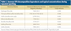
Eliminating SF6 will reduce overall equipment maintenance costs because of the substantial effort required to maintain SF6 leak rates at the regulated limit of 1% or lower. Currently, fixing a single SF6 leak costs US$25,000 on average. These costs have three components: the cost of replacing gas lost from chronic leaks, the cost of replacing flange O-rings at 10-year intervals and the cost of managing toxic by-products resulting from electrical discharges that occur within SF6-insulated equipment (Table 1).
Maintenance costs can vary greatly depending on the equipment manufacturer. PG&E historically has used two suppliers for SF6 GIS and DTCBs, and historical maintenance costs between the two have varied significantly.
The supplier with the lowest initial cost (vendor A) has had a significantly higher total cost of ownership over the life of the equipment (Table 2). In addition to the cost to repair SF6 leaks, vendor A equipment requires a biennial application of silicon grease to the flange joint and replacement of the flange O-ring seal after 10 years of service to maintain the design leak rate of 1%.
At two newly installed GIS, using equipment installed and manufactured by vendor A, most of the flanges were found to be leaking SF6 in excess of PG&E’s specification during the commissioning of the equipment. PG&E’s equipment specification requires the GIS supplier to test all flanges on the newly installed GIS equipment for SF6 leaks. The utility estimates it spent more than US$1 million on rework to lower the SF6 leak rates of the GIS equipment during its first year of ownership alone.
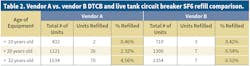
While PG&E has about equal units of equipment from vendor A and vendor B, its SF6 leakage data shows vendor A equipment represents 80% of the annual SF6 leak repairs, while vendor B equipment represents 10% of the annual SF6 leak repairs. While both vendors start with approximately the same percentage of SF6 refill (0.4%), vendor A’s equipment SF6 leaks increase (4.56%) as its equipment ages. Field experience and the maintenance data show vendor A’s SF6 sealing system starts to fail at roughly the 10-year mark. After 10 years of operation, vendor A’s equipment leaks SF6 frequently and with higher volume of SF6 than vendor B’s equipment.
Because PG&E maintains a corporate-wide SF6 leak rate below 1% of inventory, adding SF6 gas and repairing SF6 leaking equipment drives the utility’s SF6 equipment cost. PG&E has four guidelines to address the management of SF6:
- Fix all SF6 leaks.
- Only purchase equipment with the lowest SF6 leak rate.
- When possible, purchase equipment that does not contain SF6.
- Manage SF6 inventory with accountability.
As a result of this analysis, PG&E’s first step in reducing its SF6 leak rate was to terminate purchases of SF6 equipment with a higher percentage of chronic leaks (vendor A), as indicated by the field data. The utility’s second step was to evaluate the alternatives to SF6 for GIS. PG&E realized a reduction in DTCB maintenance cost when it switched from SF6 DTCB to dry-air/vacuum DTCBs, so the utility’s goal was to reproduce those savings with GIS equipment.

Equipment Testing
To test for an SF6 leak at the GIS flange, PG&E used a DILO Co. Inc. SF6 Leak Pointer (part number 3033-R002). Bagging and testing of flange joints were conducted by the utility’s quality engineers. All test results were recorded.
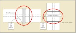
Plastic is secured around the circumference of the GIS flange, securing both sides of the plastic to the GIS housing with duct tape. The plastic does not need to be taped to the GIS, but the tape does need to provide a secure band that tightly grips the GIS. A pocket needs to be provided at the bottom of the bag to allow any SF6 to collect in the pocket.
Plastic sheeting for bagging needs to be 3-mm thick at a minimum. All joints and flanges should be wrapped in plastic to form a bag. The leak test is performed on each bagged joint or flange after 24 hours has elapsed. Without significantly disturbing the bag, a small incision is made above the pocket. The nozzle of the SF6 detector is inserted into the small incision and fed into the pocket at the bottom of the bag (Figure 1).
When the SF6 detector does not alarm, this is considered a passed test (an SF6 leak does not exist). If the SF6 detector beeps but the beep is not sustained, the test is not considered a pass or fail. If the SF6 detector stays continuously alarming, this is considered a failed test, or a positive indication of an SF6 leak that exceeds PG&E’s allowable leak rate. In the case of a failed test, the GIS equipment supplier is instructed to fix the SF6 leak.
Dry-Air/Vacuum Alternative
PG&E evaluated alternative technologies that would replace SF6 and concluded dry-air/vacuum was the most cost-effective alternative. The utility purchased three 72-kV dry-air/vacuum DTCBs prior to Jan. 1, 2009. Based on good results over the last 10 years, it no longer purchases new 72-kV DTCBs that use SF6. More than 30 72-kV dry-air/vacuum DTCBs currently are installed, resulting in reliable service and reduced maintenance cost.
With the success of dry-air/vacuum DTCBs, PG&E evaluated the technology for GIS applications. The utility’s first purchase of a dry-air/vacuum GIS was for its Evolution substation at the Livermore, California, U.S., training center. Most recently, the utility purchased a second dry-air/vacuum GIS for a 115-kV, 50-kA, 3000-A multi-bay GIS at its new Hunters Point substation. It also currently is evaluating this for its Rio Oso substation rebuild.
Supplier Evaluations
PG&E’s sourcing department completed a strategic supplier evaluation to identify dry-air/vacuum GIS suppliers. Dry-air/vacuum circuit breakers use vacuum interrupters for switching functions and treated air, known as dry air, as the insulating medium. The combination of using a vacuum interrupter within a dry-air-insulated container eliminates the use of SF6 for HV live-tank circuit breakers (LTCBs), DTCBs and GIS.
The first 72-kV, 40-kA dry-air/vacuum DTCBs were placed into service in the U.S. more than 10 years ago. Four major equipment manufacturers were identified as offering this alternative in their product line. PG&E invited all of them to participate in a request for information (RFI) based on their commercially installed products and ability to meet PG&E’s requirements for SF6 alternatives.
Three suppliers responded to the RFI. All had commercial products and experience with dry-air/vacuum GIS at the 72-kV level and a stated capability to expand their dry-air/vacuum product offerings to 145 kV for GIS. PG&E is planning for its first 115-kV, 50-kA, 3000-A dry-air/vacuum DTCBs to be installed in early 2021.
Technical Evaluation
PG&E’s standards engineering, projects engineering and sourcing quality teams evaluated the merits of each company’s GIS. The evaluation was technical in nature and independent of costs, and it included input from other California utilities. The technical evaluation consisted of:
- Quality audits of each manufacturers facility, reviewing their quality program, manufacturing failure rates, factory acceptance testing results and performance under warranty data
- An engineering design-based review of the equipment, failure analysis, review of the type testing reports and human factors review
- Compatibility with PG&E’s existing substation design and operating procedures.
Based on results and inputs, PG&E recognized the acceptance of multiple suppliers for dry-air/vacuum GIS was preferred, so no supplier was eliminated on technical issues and the 72-kV RFI was closed. All three suppliers were approved as potential quality suppliers for 72-kV GIS equipment suppliers; however, the project was canceled for nonrelated issues.
Cost and Availability
PG&E’s electric transmission and distribution (ET&D) material sourcing group issued a request for proposal (RFP) for a 115-kV, 40-kA, 3000-A GIS to the three GIS suppliers that responded to its 72-kV RFI. The RFP enabled PG&E to evaluate the commercial viability and relative costs of the three companies. The three suppliers’ pricing was similar; however, only two could meet the utility’s proposed schedule.
Based on the results of the RFP, PG&E standards engineering traveled to Germany to review in person one supplier’s manufacturing facilities and research and development technical centers to confirm information provided in the supplier’s RFP. Reviewing the technology and manufacturing in person afforded PG&E the ability to understand further the different product development steps, manufacturing equipment requirements (larger vacuum bottle ovens) and level of type testing required to bring this new technology to market.
This factory visit gave even greater insight into the technology and PG&E the opportunity to ask questions that never would have been considered from simply reviewing answers provided to an RFP.
Final Evaluation
PG&E’s final evaluation of the three companies was based on three major categories: technical, regulatory and commercial. The evaluation was made by a multidisciplinary team. The engineering and quality departments evaluated the technical merits of the three alternatives. Sourcing specialists evaluated the commercial merits, while regulatory affairs personnel evaluated the three alternatives against pending California greenhouse gases regulations. All three groups had the same objectives of reducing future cost of ownership while maintaining grid safety and reliability.
Based on the evaluation, it was concluded the most cost- effective option for PG&E was to procure technology to replace SF6 in GIS with the same dry-air/vacuum technology that replaced SF6 in the DTCBs. This technology has more preferred properties than the other alternatives:
- Dry-air/vacuum is the most extensively available commercial product with thousands of DTCBs and hundreds of GIS installed around the world.
- Dry-air/vacuum has zero GWP and no toxic by-products.
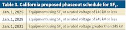
- Dry-air/vacuum will meet the proposed CARB phase-out schedule as outlined in the draft regulation (Table 3).
The leak rate from dry-air/vacuum technology is exempt from California’s state mandatory annual reporting (a significant cost savings for California utilities).
- Dry-air/vacuum GIS technology is available from multiple suppliers.
- Dry-air/vacuum is the lowest-cost life-cycle option at present.
- Dry-air/vacuum has been tested up to 65-kA interrupting current and 230-kV rated voltage.
From the three qualified GIS suppliers that used dry-air/vacuum, one could not meet PG&E’s schedule, so the decision came down to the initial cost of the equipment. Based on the utility’s RFPs to multiple suppliers for dry-air/vacuum GIS, the initial cost of a dry-air/vacuum GIS is approximately 10% higher than traditional SF6 GIS, but the utility forecasts its total cost of ownership over a 30-year operating life will be significantly lower with dry-air/vacuum GIS.
For more information:
DILO | https://us.dilo.com
About the Author
Thomas Rak
Thomas Rak ([email protected]) is a manager of Substation and Transmission-Line Standards Engineering at PG&E. He graduated from New Jersey Institute of Technology with a BSEE (power concentration). He earned his Master of Engineering from Portland State University and earned his Professional Engineering license in California. Tom has experience in distribution, substation and generation design engineering.