Retrofitting Fire Protection in a Confined Substation
A growing problem utilities encounter is the need to add fire protection with oil containment to meet today’s standards when upsizing transformers and other equipment in confined open-air substations not originally sized for such large-scale improvements. Growing population densities with increasing electrical power demands in addition to fewer options for utilities to acquire land for substation projects with greater fire protection standards is pressuring the power industry to squeeze more infrastructure into smaller areas.
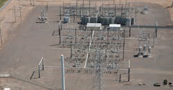
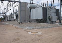
Salt River Project (SRP) was faced with this challenge at its Papago Buttes receiving station, originally built in 1964 with a small footprint and without oil containment or fire protection at its four 230/69-kV transformers. To meet today’s requirements for oil containment and fire protection, the utility needed to expand Bank 1 and Bank 2 on the north half of its receiving station with two larger transformers.
To meet this challenge, SRP’s team worked with AECOM to develop innovative solutions, including an underground corrugated steel pipe (CSP) tank; a custom overflow catch basin; two rock-filled basins lined with high-density polyethylene (HDPE), encompassing existing foundations with varying depths and overflow connections; a strategically placed firewall; and a unique cable trench cover system to protect the station’s vital control cables in the primary trench from burning oil in the event of a fire.
Scoping the Job
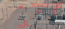
SRP needed to expand Banks 1 and 2 to increase capacity and remove an old 230/69-kV transformer from Bank 2 that was at risk of failing at the Papago Buttes receiving station before the 2017 summer peak electrical loads. The project site is confined to a small area constrained by a critical access drive and set of capacitor banks located north of Bank 1 as well as the site’s primary cable trench located south of Bank 2. Both banks were originally constructed without fire protection or oil containment, which needed to be added to meet today’s requirements.
The major electrical equipment for this project involved the following components:
• Salvaging the 322,000-lb (146,057-kg), 180-MVA transformer from Bank 1 and moving it into service on the existing foundation in Bank 2, after removing and scrapping an old transformer from Bank 2 as well as removing a sound barrier wall from the west side of Bank 2
• Increasing Bank 1 with a much larger 666,900-lb (302,500-kg), 280-MVA transformer; demolishing and reconstructing multiple foundations; and increasing steel structures with a wider dead-end to hold the 230-kV, 69-kV and drop lines
• Combining oil containment for a volume of 100% that could spill from either transformer, plus a 50% increase for the potential of additional water to meet today’s applicable standards.
To meet the challenge of providing fire protection and oil containment, the SRP project team developed an innovative system that included these features:
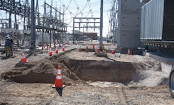
• An 18,700-gal (70,787-l) underground corrugated metal pipe tank located north of Bank 1 and under the access drive
• A custom cast-in-place concrete overflow catch basin
• Two surface oil-containment rock-filled basins, encompassing the Bank 1 and Bank 2 transformers with an under-rock weir overflow connection
• A new 30-ft (9.1-m) by 33-ft (10-m) firewall
• A unique cable trench cover system at the north perimeter of the Bank 2 oil basin.
Underground Tank
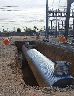
SRP had never used a solid-wall CSP underground tank to add oil containment outside a surface basin. Commonly used in residential and retail site developments for storm-water retention, this technology was adapted to capture oil that can overflow from transformer banks in the event of a fire. This underground solution was needed to keep the area north of Bank 1 open for critical truck access.
Contech Engineered Solutions fabricated the tank components, and SRP construction crews assembled and installed it with the following key features:
• An 84-inch (2130-mm)-diameter CSP with 5-inch by 1-inch (125-mm by 25-mm) corrugations delivered in three 21.67-ft (6.6-m)-long sections, for an overall length of 65 ft (19.8 m) and a capacity of 18,700 gal (70,787 l)
• Dual 36-inch (900-mm)-diameter access manway risers — one at each end of the tank with ladders and HS-20 rated solid lid covers, encompassed by 5-ft (1.5-m)-diameter reinforced concrete slabs
• All-galvanized steel components, including an 18-inch (450-mm)-diameter CSP stub-out at the east end of the tank connecting to the overflow catch basin
• An excavation depth limited to 10 ft (3 m) to avoid impacting adjacent foundations
• Controlled low-strength material backfill to ensure compacted fill below the tank’s spring line
• Approximately 2.5 ft (0.76 m) of coverage over the CSP tank.
A Custom Basin
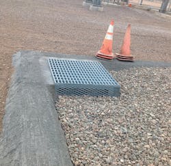
SRP designed and constructed a custom cast-in-place reinforced catch basin to capture and route overflow from the rock-filled surface basins to the underground tank. Located in the southwest corner at the low point of the Bank 1 basin, the concrete catch basin has 6-inch (152-mm)-tall openings at the top north and west sidewalls to intercept overflow. The openings are covered with expanded steel grating to hold back the fire-quenching rock. The catch basin outfalls near the east end of the underground tank through the 18-inch (450-mm)-diameter CSP stub-out.
Surface Oil Containment
SRP added two surface oil-containment, rock-filled basins encompassing the Bank 1 and Bank 2 transformers to meet current standards for quenching burning oil underneath loose rock with a minimum 1-inch (25-mm) diameter. The walls and side berms of the basins are constructed of shotcrete over a geomembrane fabric covering an HDPE liner. The depths of both basins needed to vary from approximately 5.5 ft to 1 ft (1.7 m to 0.3 m) to maintain structural earth support around existing dead-end structure pier foundations and maximize volume away from the structures.
The Bank 2 basin, which encompasses the 12,000-gal (45,425-l) North American transformer, has a capacity of 11,200 gal (42,397 l) to capture approximately 90% of its oil. To meet today’s requirements to provide 150% of the transformer oil, overflow from Bank 2 outfalls into the Bank 1 basin at a weir set approximately 6 inches (152 mm) below the top of the rock and aligned off the south end of the firewall.
The Bank 1 basin encompassing the 27,270-gal (103,228-l) Waukesha transformer has a capacity of 22,000 gal. (83,279 l) to capture approximately 80% of its oil. To provide 150% of its oil, overflow from Bank 1 outfalls into the northeast catch basin and underground tank.
Firewall Protection
SRP strategically placed a 30-ft (9.1-m) by 33-ft (10-m) firewall between the Bank 1 Waukesha and Bank 2 North American transformers, which have approximately 40 ft (12 m) of separation. Today’s standards recommend transformers of this size with less than 50 ft (15 m) of separation have a firewall for fire protection from each other.
Cable Trench Covers
A two-part removable cover system was developed to protect approximately 28 ft (8.5 m) of the station’s main cable trench aligned through the potential oil spray zone of the Bank 2 North American transformer.
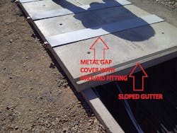
SRP worked with Trenwa Inc. to develop 14 custom precast cable trench covers sloped with embedded side valley gutters that can catch and drain oil runoff from the cable trench into the Bank 2 basin. These covers are sloped to drain north with a 2.5-inch (64-mm) height on the low north side and a 3.5-inch (89-mm) height on the south side. Their lengths span over the 3.5-ft (1-m) cable trench, and they are each 2 ft (0.6 m) wide. Trenwa custom fabricated one mold to cast these covers. They each weigh 255 lb (116 kg) and are machine-lifted with embedded threaded taps.
SRP’s mechanical shop fabricated 13 steel pieces to fit over the precast cover gaps, precluding burning oil from seeping through them and ensuring oil runs off through the valley gutters. These gap covers are 8-inch (203-mm)-wide 10-gauge steel and include welded bottom plates to secure them between the precast cover gaps. They are grounded at their ends with tapped fittings to a #4/0 stranded copper bar that connects to the station ground grid.
Project Completion
SRP and AECOM met the challenge of adding fire protection and oil containment to both upsized transformers per today’s standards in the constrained Papago Buttes receiving station. By implementing practical solutions from the non-substation development industry, the team found feasible resources to budget, schedule, acquire materials and construct them in a unique configuration. ♦
Matthew P. Jaramilla has been a senior civil engineer in the substation design group at Salt River Project for 10 years, with project management experience on large-scale transmission and substation projects. He also spent 11 years working as a consultant on land development, transportation, water/wastewater, flood control and environmental permitting projects. He holds a BSCE degree from Arizona State University and is a registered professional engineer in Arizona.
David E. Mickanen is a project manager and principal civil engineer in AECOM’s Phoenix, Arizona, U.S., office. He has more than 25 years of project experience, including power facilities with renewable energy and other infrastructure. He holds a BSCE degree from San Jose State University and a MBA degree from Aspen University. He is a registered professional engineer in multiple states including Arizona.
Check out the October 2017 issue for more articles, news and commentary.
About the Author
Matthew P. Jaramilla
senior civil engineer
Matthew P. Jaramilla has been a senior civil engineer in the substation design group at Salt River Project for 10 years, with project management experience on large-scale transmission and substation projects. He also spent 11 years working as a consultant on land development, transportation, water/wastewater, flood control and environmental permitting projects. He holds a BSCE degree from Arizona State University and is a registered professional engineer in Arizona.
David E. Mickanen
David E. Mickanen is a project manager and principal civil engineer in AECOM’s Phoenix, Arizona, U.S., office. He has more than 25 years of project experience, including power facilities with renewable energy and other infrastructure. He holds a BSCE degree from San Jose State University and a MBA degree from Aspen University. He is a registered professional engineer in multiple states including Arizona.
