When T&D Foundation Construction Gets Messy: Early Collaboration Provides Best Value
Any time you are doing foundation design and construction for major transmission lines and other power delivery assets, you are working in the unknown world of the subsurface. As a designer and part of an owner-contractor team, you are served best by early and constant communication, the ability to react and adapt, and the knowledge that something not in the plan will always happen.
Early collaboration is a way for the owner, engineer and contractor to not only identify obstacles, gauge constructability, share ideas and study alternatives, but also to lower the probability of fault-finding during construction. That is why the entire team, including the owner, needs to have all the information available about soil conditions and obstacles, rocks or utilities to design effective foundations and avoid costly overruns and redesigns, as we have covered in the first two articles in this series.
The third article in this series illustrates how a communicative, adaptive philosophy is necessary for foundation design and construction success.
The artesian water battle
River crossings provide some of the greatest challenges for below and above-grade design. Extreme terrain changes, poor soils and above-average span lengths contribute to the challenges. This particular story involves a major Midwest transmission line crossing a large river valley. Besides crossing the river channel, the line traverses an ancient river valley approximately 1.5 miles wide. It features glacial soils, shallow weathered bedrock, deep organics and alluvial deposits.
The routine geotechnical investigation for the three structures immediately north of the river yielded unique data that would provide challenges for foundation design and construction.
The first location was rejected after the auger struck a suspended boulder. After drilling a grid of power auger borings, a clear spot was identified for a 13-ft diameter permeant casing to be vibrated in and drilled out. The casing was needed in this location because of loose saturated sands causing a high risk of cave in.
At the second location, the geotechnical boring crew encountered 23 ft of alluvial clays, followed by 15 ft of loose, silty sand and then very soft alluvial lean clay extending to 60 ft below the surface. At that point, the driller encountered strong artesian water. That hole was abandoned. A specialty contractor was brought in to backfill the hole with cement under high pressure. A second hole was drilled to identify the material below the 60-ft depth and to measure the artesian head pressure for use in foundation design.
At the third hole location, the drillers encountered artesian conditions at 38 ft after penetrating loose poorly graded sand. The initial hole was abandoned and pressure grouted. A second, exploratory hole was blind-drilled to 52 ft and sampled to a depth of 55 ft before hitting refusal on bedrock. The bedrock was classified as light gray and pink, wet, highly weathered granitic gneiss.
Through collaboration with the owner utility and the contractor, designers then considered two different construction methods — a traditional drilled shaft with permanent steel casing or micropiles with a large pile cap and pedestal to house the anchor bolts. After evaluating both designs, the drilled shafts with permanent casing alternative was chosen. Reasons included: less soil disturbance; fewer unknowns; fewer penetrations of artesian confining layer (one shaft versus numerous piles); no need for de-watering; contractor capability (micropile installation would require specialty subcontractor); construction schedule and time required for foundation construction; contractor experience with vibratory hammer and scheduled use of vibratory hammer for other river crossings, saving rental and procurement costs.
Artesian flows a problem at third location
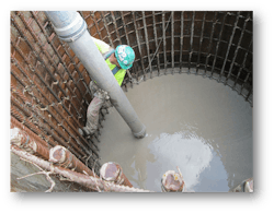
During construction, all casings were driven to the design depth through the artesian stratum into competent material, thus sealing off the water. For the first two foundations, the casing was effective in shutting off the artesian flow and the foundations were poured as “wet holes” using pump trucks and tremie pipes.
However, when excavating inside the casing at the third location, water continued flowing from the excavation. It was determined that the water was flowing through the highly weathered and fractured bedrock. After it was evident that the casing would not stop the flow of water from the hole, to combat the head pressure, the contractor welded on an additional 9 ft of casing — resulting in a total of 14 ft of casing above the ground surface.
The additional fluid head was successful in controlling the artesian flow. The plan also included the use of a custom-designed drilling mud based on the previously completed pressure head testing at the structure location. A drilling pad was constructed to allow for drilling over the 13 ft of projected casing.
All drilling spoils were transported to a containment pit and subsequently pumped to an adjacent drying pit. Once dry, the spoils were loaded into trucks and hauled offsite. Once the rebar cage was set, the contractor began installing concrete using pumping and tremie methods. As the concrete was introduced to the bottom of the hole, the slurry was pumped into an onsite holding tank. Once the concrete was pumped to the elevation at which it was able to overcome the artesian pressure, the remaining slurry was removed from the top of the concrete using a vacuum truck and the anchor bolts were set using standard procedures.
Following the completion of the foundation pour, water continued to flow both outside and inside the permanent casing. Water from the artesian aquifer flowing up along the foundation is problematic both environmentally and structurally. Water can carry fine soil particles, eventually eroding the resisting soil supporting the foundation. This phenomenon is known as piping. If left unmitigated, it can cause surficial subsidence and voids beneath the ground surface adjacent to the casing, excessive structure deflections or worse — foundation failure. On the interior of the casing, the presence of water during cold temperatures can cause cracking of the concrete.
A specialty contractor was procured, and a plan was developed to mitigate the seepage of groundwater up the drilled shaft because of the artesian groundwater conditions. A grouting plan was broken into two parts. Sodium silicate cement was used to seal the perimeter of the drilled shaft. A series of casings were installed around the perimeter of the shaft and drilled to the boundary of the upper cohesive confining layer and the water-bearing sand layer.
Controlled pressure injection was used, and the casing withdrawn in 1-ft increments, essentially creating rings of grout around the perimeter of the shaft. Densification of the lower permeability soils was obtained by moving the surrounding soils radially from the growing rings of grout, thereby closing the conduit through which the water had been following to the surface. As an added safety precaution against piping of fines, a progressive filter layer was installed around the perimeter of the casing to trap any fine soil particles. The system consisted of gravel underlain by sand.
To control the interior water, urethane grouting was used. A trench was dug around the shaft and a series of holes and relief ports were installed around the perimeter of the casing. Urethane was pumped into the void, allowing the pressure to carry the material up and out of the exposed end of the casing above the ground surface. The perimeter and interior grouting procedures were successful in stopping all flow around or within the foundation casing.
Because of the challenging subsurface conditions at these foundations, costs were well above average for structures of comparable size and loading found in other areas of the project. The third structure did not have the largest diameter foundation, but it was by far the most expensive. This was because the foundation required the use of specialized drilling techniques and required post-construction pressure grouting to stop artesian flow from surfacing around and within the shaft.
The three structures of our example project are a prime example of how engineers working with the owner and contractors can develop a practical solution to very challenging conditions. As with any other work below the ground, transmission foundation design and construction often encounter unforeseen conditions that need to be dealt with in a timely manner because of the importance of scheduling and the associated cost of delay.
About the Author
Lucas Karels
Lucas Karels of the Minneapolis office of Stanley Consultants has 12 years of project management and structural engineering experience and specializes in above-grade and below-grade transmission and substation design. Karels is a licensed professional engineer in 10 states, and a published author and speaker on transmission design and project management.

