Structure Flexibility Affects Line Clearance

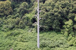
Self-supporting steel monopoles with concrete drilled-shaft foundations continue to be a popular choice for the installation of new transmission structures for voltages up to and including 500 kV. A design of these structures that is based principally on strength can result in flexible structures that endure large deflections under various climatic loading conditions.
Large structural deflections can have a significant impact on the transmission line system. These deflections can affect wire clearances and tensions, and may violate equilibrium assumptions between the wire and structure system. Deflections can complicate the stringing and sagging of the conductors and cause secondary moments on structural members. Extreme deflections can result in appearance problems. As a result, most design codes and utility practices specify maximum limits for structure and foundation deflections.
However, there are currently no standard criteria for setting pole and foundation deflection limits, which means the limits vary from utility to utility. In some instances, steel pole deflection criteria limits are placed on service loads, while in others, limits are placed on deflections under extreme loads. Often, these limits are arbitrarily set based on a utility’s past experience. Foundation performance limits of 2 inches to 4 inches (51 mm to 102 mm) of lateral deflection and 1 degree to 2 degrees of rotation at the top of the shaft are typical for extreme load cases. Such criteria are rooted in ensuring geotechnical stability as opposed to acceptable rigidity under service loads.
Typically, a line is designed in a linear procedure by considering independent components (wires, structures and foundations) with loads generated from the adjoining components. The wire design is based on a limiting tension, which is defined by weather conditions, the initial sagging tension and rigid structures at the end of each section. Structure designs are usually based on wire loads generated, assuming the structures are rigid and the insulator attachment points to the structures do not move. Foundations designs are based on structure support reactions.
Usually, the only interaction between wires, structures and foundations that is considered is in the determination of design loads for each component. This method is adequate for structural design because, if pole and foundation movements were considered, the attachment point loads typically would be reduced. However, this approach does not allow for evaluation of how the system’s flexibility impacts wire geometry, namely sag and blowout.
With this in mind, CEATI International teamed with DiGioia Gray & Associates to perform a parametric study to assess the impact of structure and foundation flexibility on conductor sag, clearances and constructability. The goal of the study was to develop steel pole and foundation deflection recommendations that would ensure structures and foundations have the necessary rigidity to keep wire movements, which cannot be captured using rigid structure assumptions, at reasonable minimums. The resulting criteria are applied to operational load cases and can be incorporated into line design without adding complexity to the process.
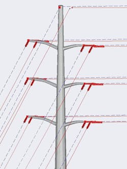
The parametric study investigated the impact structure and foundation deflections have on wire geometry for a representative 138-kV double-circuit, self-supporting steel pole line. The study included multiple structure types with spans ranging from 400 ft to 1500 ft (122 m to 457 m). Structures were designed using PLS-CADD Level 2 modeling assumption for loads, and PLS-POLE nonlinear finite element analysis for structure design. These lines and structures were then analyzed in PLS-CADD using both the rigid structure assumptions of Level 2 and flexible structure assumptions of Level 3 analyses to capture the difference in wire sag for both operational and extreme load cases. These differences represent the unmodeled wire behavior not captured when using typical PLS-CADD Level 2 design procedures.
To capture the impact of foundation movements, a drilled shaft was designed for each pole in the parametric study using liberal deflection criteria and weak soils to maximize foundation movements. The foundation rotations were calculated using EPRI’s foundation design program MFAD 5.1 to predict maximum foundation movements for each structure. The foundation movements were used to calculate movements in the wire attachment points to calculate sag changes.
Pole Flexibility on Wire Geometry
The first step in the study was to create a series of representative transmission lines. A 138-kV double-circuit line was selected for analysis. Four transmission lines were used in the study, all containing tangent 10-degree running corner, 30-degree and 60-degree strain, and full dead-end structures. Each line had constant spans of 400 ft, 800 ft (244 m), 1200 ft (366 m) and 1500 ft. Pole heights were determined assuming rigid pole structures and a level ground surface. For this study, the line was designed for the National Electrical Safety Code (NESC) heavy-loading district and a noncoastal region, in which the 50-year wind load is 100 mph (161 kmph) or less.
For each of the line geometries, four different families of poles were designed with pole deflection limits ranging from no limit down to a maximum pole tip deflection of 0.5% of pole height under operational load cases. These operational load cases represented loading conditions where clearances are specified by NESC and the line is expected to operate without outages. For the study, operational loads of 0.5-inch (13-mm) ice, 6 psf (30 kg/sq m) wind and a maximum operating temperature of 212°F (100°C) were used.
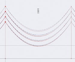
The wire sensitivity analysis was carried out by populating the line with all structures that meet a particular design criterion. Each line was first analyzed in PLS-CADD using a Level 2 analysis, and wire sags and clearances were recorded. These results were considered to be the values that would be obtained during a typical line design and used for clearance checks.
Next, each line was re-analyzed using a Level 3 analysis and the same results were obtained. The Level 3 analysis was considered to be a more accurate representation of the true behavior of the system. The differences between the two analysis methods were considered “unmodeled” effects not captured when performing the typical Level 2 design procedure, but would exist in the field due to structure flexibility.
It was found the most significant increase in sag was from the 0.5-inch ice condition, where the unmodeled sag was as large as 1.5 ft (0.5 m) for long spans, using a 60-degree strain pole or 2 ft (0.6 m) for a dead-end pole, with unrestricted deflection limits.
A cost assessment was done to determine the most efficient method for mitigating the unmodeled wire movements. More stringent deflection criteria resulted in heavier structures; however, the unmodeled sags also could be accounted for with increased structure height. For each family of poles, the amount of steel required to increase the pole’s stiffness was compared with the amount of steel required to increase its height by the calculated value of unmodeled sag.
It was found that if the goal of restricting pole deflections is to control sags and clearances, then increasing pole height is a more economical method for mitigating clearance violations caused by pole flexibility, in lieu of imposing a more stringent stiffness requirement. A deflection criterion of 1.5% pole height, under operational loads, provides a low-cost pole option for structures within the scope of this study and results in a roughly 10% weight increase, compared with a design in which deflection limits were omitted.
Impact of Foundation Movements
Foundation design is typically performed after the structural design of the poles has been completed. While it is common to assume some level of foundation rotation on the structural design of the poles, it is less common for anticipated foundation movements to be incorporated in line design. To better understand the impact of foundation movements, a study was done to determine the sensitivity of conductor-to-ground clearances to both translational and rotational foundation movements.
The adopted approach was to look at full dead-end structures and strain structures with line angles between 10 degrees and 60 degrees. A foundation displacement and rotation into the bisecting angle reduces the ahead and back spans, and increases wire sag. For the dead-end structure, it was assumed the significant wire loads were applied only to one side of the pole, analogous to a termination structure. In this case, the pole was assumed to move (deflect or rotate) in the direction of the span instead of along a bisecting angle.
Wire sags were determined for both the rigid and flexible foundation assumptions using parabolic approximations of the governing catenary equations and accounting for wire elasticity.
The foundation rotation (and therefore the pole rotation) was incrementally increased for each combination of pole height, span and line angle; the resulting sags were calculated developing a relationship between foundation movements and sag increases. By using the same structure and span lengths as those used in the steel pole parametric study, a direct comparison between the impact of pole deflections and foundation movements could be made. It was determined that sag increase as a result of foundation movements was more heavily dependent on line angle as opposed to span length. The larger the line angle, the greater the potential negative impact foundation movements could have.
Once a relationship between foundation movements and wire sag was established, the next step was to determine realistic foundation movements that may occur for each type of structure in the pole families. MFAD 5.1 was used to design a foundation for each pole from the pole flexibility study, based only on geotechnical strength under extreme loads in below-average soil with liberal deflection limits.
The resulting designs were considered the most flexible foundations that could be realistically designed in practice. Calculating the deflections of these foundations under operational loads and using the relationships between foundation movement and sag, an anticipated sag increase as a result of foundation movements could be calculated for each pole.
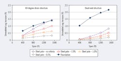
The plot below shows the unmodeled increase in sag attributed to structure deflections (dashed lines) and foundation movements (solid line) for a 0.5-inch ice event for a 60-degree strain and full dead-end pole. For the 60-degree strain structure, the magnitude of unmodeled sag, associated with foundation movements, is roughly equivalent to the unmodeled sag associated with a pole with no applied deflection criteria. For dead-end poles, the plot shows that measures to reduce unmodeled sag should focus on limiting foundation movements, not pole stiffness.
The results of this study suggest foundation performance criteria should be set based on line angle, as the impact of foundation movements are amplified for large angle and dead-end structures. It also is recommended that foundation design includes deflection and rotation limits for serviceability load cases where it is desired to control sag. These limits can be checked in addition to any extreme load limits adopted by a line designer or owner. This is a noted departure from current foundation design practice where serviceability limits are typically the same for all structure types and line angles throughout a project and specified only for extreme loads.
Flexibility of the Whole
The flexible pole, the moving foundation and their interaction with the wire system can push the limits of design clearances. Wire sags predicted using a flexible support system can exceed those predicted assuming a rigid support by 1 ft or more. However, new deflection criteria for both poles and foundations that will limit unmodeled wire sag to reasonable minimums for even the most extreme cases studied is achievable without significant increases in structure or foundation cost. All it takes is a small shift in the paradigm for how serviceability limits are defined.
Adam G. Bowland is a professional engineer with five years of experience working in the power delivery industry. He holds a BSCE degree from Carnegie Mellon University as well as a master’s degree and Ph.D. in structural engineering from Virginia Tech. He is a senior engineer in the transmission engineering group for DiGioia Gray & Associates and a member of ASCE.
Paul G. Cass is a professional engineer working in all aspects of transmission line siting, design, construction and maintenance. He holds BSCE and MSCE degrees, specializing in geotechnical engineering, from the University of Pittsburgh. He worked for 26 years as a civil, structural, geotechnical and transmission line engineer for Duquesne Light. Currently, he is a senior consultant in the transmission engineering group for DiGioia Gray & Associates. He is life member of ASCE and a member of IEEE.