Mississippi Crossing
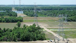
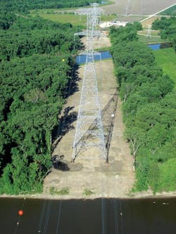
Positioned between two levees approximately 6000 ft (1829 m) apart, the construction of a 345-kV, double-circuit river crossing over the Mississippi River inundated Ameren Transmission Company of Illinois with challenges. As part of a portfolio of multi-value projects approved by the Midcontinent Independent System Operator, this river crossing is 1.56 miles (2.51 km) long, connects the Maywood substation in Missouri and the Herleman substation in Illinois, and is part of the Illinois Rivers Transmission project — 385 miles (620 km) of transmission from Palmyra, Missouri, to the Indiana state line in Illinois.
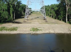
Designed as a six-tower crossing — with towers ranging from 167 ft to 385 ft (51 m to 117 m) in height — three of the lattice steel structures fall within the levee system of the Mississippi River, two of those on islands. The team faced a challenging obstacle: How could the crossing be constructed safely and productively within the floodway of the river and yet stay within the confines of the more than 30 permits and authorizations required for this project?
Access Challenges
Three of the towers, one in Missouri and two in Illinois, were accessible from county roadways. The installation of driveway entrances off county roads and matted access within the right-of-way provided traffic lanes to and from these towers.
A fourth tower fell within the floodway, less than 300 ft (91 m) from the levee in Missouri. In working closely with the levee district, an agreement was reached to enable access to this tower by constructing a temporary access road over the existing Missouri levee. Daily monitoring of the roadway and weekly levee inspections were performed for the duration of construction. A post-construction flood analysis also was performed.
Multiple solutions were proposed for access to the two remaining island towers. Proposals included the use of floating barges, temporary bridges and causeways from the land side of both islands. Varying river levels and the requirement to maintain public access through the side channels of the river during construction eliminated these options. With extensive input from project stakeholders, it ultimately was decided to access both islands from the main channel of the river.
For Fabius Island in Missouri, use of a temporary stabilized shoreline on the river side of the island created a durable base for two 50-ft (15-m) steel ramps used to walk equipment and materials off the barges.
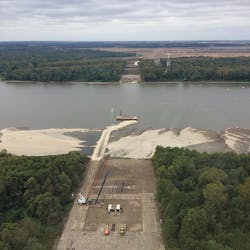
Ward Island in Illinois presented its own set of complexities. Historical data shows portions of this island have been underwater more than 50% of the year. In addition, the river side of the island is bordered by a sandbar that extends into the river approximately 600 ft (183 m). The sandbar made it impossible for the project’s construction barges to maintain proper draft near the shoreline, and the sandbar was not solid enough to enable tracking of equipment across the sand without some roadway stabilization.
To overcome this obstacle, the team worked with the U.S. Army Corps of Engineers, other agencies and many consultants and contractors to design a temporary causeway into the river. The causeway was designed to be 720 ft (220 m) long, required approximately 12,000 tons (10,886 metric tons) of rock and needed additional permitting commonly referred to as a no-rise certification from the Illinois Department of Natural Resources. This design provided stable and reliable access across the sandbar and established a docking area in the river for barge loading and unloading.
Geotechnical Analysis
With tower locations finalized and proper authorizations in place, Hanson Professional Services was tasked with obtaining soil borings to aid the foundation design process. At five of the towers, two soil borings were obtained at diagonally opposing legs: one of the borings included a rock core and the other was taken to a depth of 100 ft (30 m). Additional borings were not needed because relatively uniform soil conditions were discovered between the two borings at each tower.
Obtaining soil borings at the tower on Ward Island proved difficult as a result of changing water levels. River level fluctuations prevented the offloading of the drill rig on multiple occasions. After three failed attempts, it was decided the foundation design would continue using boring information from the closest towers. Once the temporary causeway was installed, the drilling crew would be able to gain access and obtain the borings. Then the soil parameters assumed in the foundation design would be verified and the design adjusted, if necessary.
Foundation Design
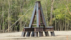
As the foundation designer, Hanson worked closely with Ameren to determine the most desirable and feasible foundation type. An existing Ameren line north of the proposed crossing — constructed in the mid-1970s — uses steel tripod foundations. This foundation type appealed to the team because it eliminated the need for delivering or producing concrete on Fabius and Ward islands. Combined with driven H-piles (HP) — rolled steel structural beams H-shaped in a cross-section — steel tripods also provided a reduction in wetland impacts for foundations within sensitive areas.
The tripod arrangement was chosen as the foundation type and consists of an all-steel tripod located under each tower leg supported by individual sections of steel HP 14x117, a nominal depth of 14 inches (356 mm) by 117 lb-ft (174 kg-m). Each tripod consists of three wide-flange steel legs: One tripod leg is vertically oriented and the other two are battered with a slope of 1.0 horizontally to 2.5 vertically to resist lateral forces. Each leg is supported by a wide-flange steel-cap beam and a group of piles driven with the same alignment (vertical or battered) as the tripod leg.
The number of H-piles supporting the tripod foundation at each leg depends on the type of tower. Each anchor tower required 10 H-piles supporting the tripod foundation at each leg, while the suspension towers required only six or eight, depending on the location and tower height. The maximum factored design loads on the piles are approximately 170 kips in compression and 130 kips in tension.
The nominal pile capacity for vertical and battered HP 14x89, a nominal depth of 14 inches and 89 lb-ft (132.5 kg-m), at five of the six foundation locations was estimated using the U.S. Federal Highway Administration method for calculation of nominal pile capacity. Because the soil borings on Ward Island were completed after pile selection, the nominal pile capacity for vertical and battered HP 14x117 at this foundation location was estimated using the Illinois Department of Transportation method.
Design and analysis of the steel tripods and steel piles were performed using the general-purpose RISA-3D design and analysis software from RISA Technologies, including the use of lateral soil springs to model the effect of the structure-soil interaction. Foundation designs were based on reactions at the base of each tower leg provided by the lattice tower designer, ASEC Inc. In addition to the base reactions provided by ASEC, other loads evaluated included wind on exposed foundation elements, and stream and flowing ice forces as applicable.
Typically, the anchor tower foundation loads were controlled by the National Electrical Safety Code C2-2012 heavy-loading combination, with some modifications by Ameren. The taller suspension towers were controlled by extreme wind load combinations applied at a skew relative to the line alignment, resulting in maximum upward and downward tripod loads at diagonally opposing tower legs.
The American Association of State Highway and Transportation Officials considers flowing ice to be an extreme load case with a low probability of occurrence. Therefore, it seemed overly conservative to apply this load indiscriminately to all load combinations. Ultimately, it was decided to include flowing ice loads in all combinations that did not include extreme wind loads. For comparison purposes only, load combinations with extreme wind loads were combined with flowing ice loads using an overload factor of 125%. Neither liquefaction nor lateral spreading as a result of liquefaction was a concern at this site.
Hanson performed a water resources investigation of the river environment and recommended the top of the tripod foundation at the base of each tower leg be 1 ft (0.3 m) above the 500-year flood elevation. This will help to preclude the accumulation of debris in the lattice tower legs, which could damage the tower members during a flood event. Hanson also performed a scour analysis with scour-depth results at the foundation locations ranging from 4.1 ft to 8.8 ft (1.2 m to 2.7 m). These scour depths were then considered in the foundation design and pile length determinations.
Various methods of corrosion protection were considered for the driven steel piles, including field-applied protective coatings, galvanizing and providing a corrosion allowance. Ultimately, heavier pile sections were selected to provide a corrosion allowance for a minimum foundation design life of 100 years. The H-piles were first sized for strength — requiring HP 14x89 sections — and then increased to account for corrosion and section loss, resulting in an increase in the H-pile section to HP 14x117.
In detailing the tripod foundations for this project, improvements were made to the previous design used for the adjacent Ameren crossing. After inspection of the existing tripod foundations on the adjacent line, some corrosion was documented on the cap beams as a result of water being trapped between the stiffeners and the webs of the cap beams.
In this crossing design, drain paths were provided for the cap beams to accommodate water accumulation during rain or flood conditions. In addition, for the foundations in the floodway, cover plates were added to fully box the wide-flange shapes forming the legs of the tripods, protecting the flange tips from localized bending as a result of ice and debris. Other design improvements to the steel tripods included oversized cap plates and additional member length, which would enable field adjustments when connecting the tripod members. The lattice towers would be connected to the steel tripods using bolted splices to heavy stub angles at each tower leg.
Access Construction
Access construction began in June 2015, with pile driving at the first foundation location beginning the following month and continuing for seven months.
Very tight pile-driving tolerances were required to connect each tripod leg to a linear group of piles with a single steel cap beam. The project specifications required piles to be driven within a plan location tolerance of 1 inch (25 mm) in each direction, with deviations greater than that to be evaluated on a case-by-case basis. Pile-driving templates and guides, as well as a semi-fixed lead driving system with a spotter, were used to help achieve the required tolerances. The maximum as-built deviation documented on the project was 1.93 inches (49.07 mm).
Pile lengths were adjusted in the field after actual pile capacities were verified using dynamic load testing on a minimum of two piles per tower, representing 6% of the total number of piles to be driven. Dynamic pile load test data was used to confirm pile-load capacity and establish pile-driving criteria for the remaining production piles.
After the piles were driven and the tripods installed, the lattice tower assembly began in October 2015, with the first lattice steel erection in November. The two tallest towers were designed in 14 body sections and six arms. The electrical contractor used cranes for erection of the bottom sections of the tower and a helicopter to lift and place each of the taller tower sections and arms. All six towers were erected within four months, followed by the installation of six bundled conductor phases, one static shield wire and one fiber-optic ground wire.
A Successful Completion
After 14 months of construction and some significant river flooding, the Herleman-Maywood river crossing was completed in August 2016. The unique access and regulatory restrictions for construction on the Fabius and Ward islands in the floodway of the Mississippi River were certainly challenging, but they were overcome with ingenuity and intense cross-disciplinary and stakeholder collaboration.
The design selection of the all-steel tripod foundations over traditional concrete was validated during construction given the number of work stoppages incurred on the islands. Thanks to a very determined and creative team, this project was completed safely and is considered an unparalleled success.
Kasey Woods is Ameren’s project manager for three river crossing projects associated with the Illinois Rivers Transmission project. She holds a BSEE degree from the University of Missouri-St. Louis/Washington University joint engineering program, is a licensed professional engineer and a certified project management professional, and has spent her entire career in the transmission sector.
Danielle Rawers is Hanson Professional Services Inc.’s associate project manager for the Illinois Rivers Transmission project river crossing and transmission line projects. She has a bachelor’s degree in architectural studies from the University of Illinois Urbana-Champaign, is a certified associate in project management, and has been working for Hanson’s power and industry market since 2013.
