Line Uprating Leads to Structural Reinforcement
American Transmission Co. and other utilities are finding high-voltage electrical transmission line and substation upgrade projects place increased structural demand on existing steel-pole support structures. Transmission line and substation engineers must find economical solutions when existing steel poles are determined to be overloaded structurally from wire upgrades, code changes, and line routing or substation layout modifications. Reinforcement solutions are available to increase the structural capacity of the existing poles, which offers advantages over structure replacement options.
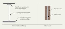
For most structural engineers, the first exposure to structure reinforcement was a steel wide flange beam reinforced with steel plates and/or steel rods. The placement of additional steel material at the top or bottom of a wide-flange shape results in an increase in the overall bending capacity and resulting stiffness of the beam. Similarly, the first exposure to stiffness-based load distribution was a built-up wood or steel beam, commonly referred to as a flitch beam. The flitch beam represents the engineering principle of load following stiffness. For analysis purposes, load is distributed to the wood and steel members in accordance with the ratio of each component’s individual stiffness to the overall stiffness of the composite member.
These two common structural augmentation examples represent the core basis for the structural engineering principles used to design reinforcement solutions that result in increased steel-pole structural capacity.
Typical Analysis
One of the first questions to answer when faced with overloaded transmission poles is whether reinforcement solutions are better than replacing the poles. Many engineering considerations and factors come into play when answering this question. In terms of magnitude of structural overload, if an existing steel-pole shaft is overloaded by 100% or more of its original capacity, the magnitude of reinforcement required is likely extensive and, perhaps, cost prohibitive. Conversely, if an existing steel-pole shaft is overloaded by 10% or so, a reinforcement solution may be much more feasible and cost effective. This situation provokes a study of viable pole-reinforcement solutions with respect to the pole-shaft magnitude of overload.
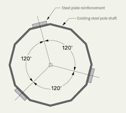
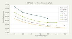
As an example, consider a basic symmetrical plate-reinforcement configuration on a steel-pole shaft. A study of this issue would include constructing a graph indicating the percentage of pole-shaft structural capacity increase, per American Society of Civil Engineers standard ASCE 48-11, based on varying pole diameters and shaft thicknesses for a typical 12-sided steel-pole shaft with three symmetrically placed 4.5-inch (11.4-cm) wide by 1-inch (2.5-cm) thick reinforcing plates. If a 36-inch (91.44 cm) diameter by 0.3125-inch (0.7938-cm) thick pole shaft were overloaded by 30%, the existing shaft could be reinforced with this plate configuration over the extent of overload, thereby avoiding replacement of the entire structure and foundation.
Blind Bolts
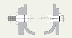
Reinforcing elements are connected to the existing structure by welding or bolting. Welding offers full composite performance of the plate and pole-shaft system throughout the entire load spectrum; however, installation of welded systems can be time consuming and costly. More recently, bolted plate reinforcement systems have been developed that are quicker and safer to install with standard construction techniques, and they offer similar structural capacity percentage increases. Bolted reinforcement systems use blind bolts to fasten the reinforcing elements to the exterior side of the existing pole shaft. A blind bolt is used when it is not possible to access the inside of the pole shaft to install the nut on a traditional bolt.
The American Institute of Steel Construction’s 14th edition Steel Construction Manual describes blind bolts as follows (on pages 7-13): “Special fasteners are available that eliminate the need for access to install a nut (Korel et al, 1993; Henderson 1996). The shank of the fastener is inserted through holes in the parts to be connected until the head bears on the outer ply. In some cases, a special wrench is used on the open side to keep the outer part of the shank from rotating and simultaneously turn the threaded part of the shank ... Manufacturers’ literature must be consulted to determine the available strength of blind bolts.”
Blind bolts, with a variety of structural capacities and installation techniques, are readily available from reputable hardware manufacturers. Manufacturers’ literature can be investigated to obtain a more in-depth understanding of installation procedures and structural design-limit states.
Pole Reinforcement Projects
American Transmission Co. (ATC) recently faced some transmission line upgrade projects where structural analysis determined existing steel poles would be overloaded as a result of the planned upgrades. Pole reinforcement was chosen to increase the capacity of existing poles, extend their asset life and avoid structure-replacement operations. ATC engineers worked with structural engineers at Paul J. Ford and Co. (PJF) to develop reinforcement solutions, including bolted reinforcement and welded reinforcement.
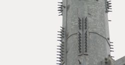
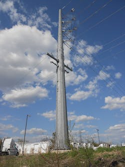
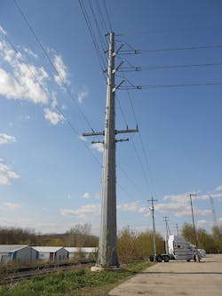
ATC reinforced a 79-ft (24.1-m) tall 90-degree dead-end steel pole that supports three phase conductors, one shield wire, and an underbuild circuit. Structural analysis indicated the existing structure was insufficient to support the required loading conditions. Rather than replacing the pole, a reinforcement solution was developed and installed. Because it was a galvanized pole, bolted shaft reinforcement was a valid option to remedy the shaft overload.
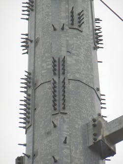
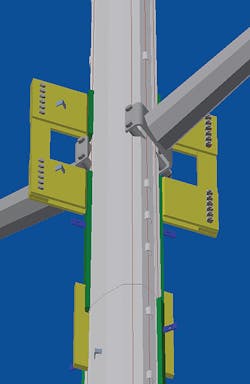
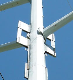
For this structure, a folded-plate solution was used. This solution is a steel plate bent to match the pole shaft’s geometry and installed across a point. The plate is bolted to the shaft flats on either side of the respective shaft point with blind bolts. The folded-plate solution offers excellent structural reinforcement efficiency because it places the reinforcing element in the location of maximum stress.
Because this pole contained an underbuild circuit, careful attention was required to orient, develop and lap the reinforcement on available flats as the reinforcing elements continued around the underbuild arms. In this case, the existing baseplate was adequate for the required loads. The vertical stiffener plates at the base of the pole are transition plates that terminate the reinforced section into the existing baseplate. Because of the reinforcement provided, the pole-shaft capacity was increased to support the required loading conditions and the fully constructed existing pole was able to remain in place.
Another ATC transmission line upgrade project included the replacement of an existing shield wire with new optical ground wire (OPGW). During the design phase, it was determined four existing steel poles in the transmission line would be overloaded as a result of the planned OPGW upgrade. Pole reinforcement was selected to remedy the overloaded pole conditions.
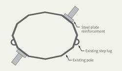
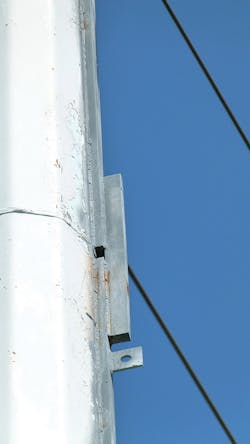
The existing supporting structures are elliptically shaped, hermetically sealed, painted steel poles built circa 1970. One of the first reinforcement design considerations was how the reinforcing elements would be connected to the pole shafts. Because the existing shafts are painted and hermetically sealed, it was reasonable to assume the inside of the shafts were unprotected. Thus, welding the reinforcement elements to the outside of the shaft was preferable to blind bolting, which would create numerous additional holes in the pole shaft by which moisture penetration could occur. The reinforcement design selected for the pole shafts consisted of a steel plate installed on two flats of the pole.
It also was determined the existing pole shafts on three poles were overloaded from the base up to the bottom conductor arm. Because the arm brackets occupied the flats needed for shaft reinforcement, an arm jump weldment was designed to reinforce the overloaded section at the lower arm projection.
Lessons Learned
ATC determined extending the asset life of the structures by using reinforcement solutions was desirable for schedule, constructability and cost reasons. The project presented design and construction challenges that were solved through creative solutions and collaboration between engineering and construction personnel. The ability to install reinforcement on the lower portions of the structures ahead of the scheduled line outage provided the construction contractor scheduling flexibility and reduced the planned outage time frame. In terms of constructability, smaller and less equipment was used compared to that in a traditional structure-replacement project. These factors along with lower material costs all contributed to project savings of nearly 20% by reinforcing the existing structures.
Thus, when existing steel poles are determined to be overloaded, reinforcement solutions are available to increase the structural capacity of the poles. In specific circumstances, reinforcement and modification operations can be performed in the field, offering advantages compared to structure-replacement operations. Reinforcing elements can be added to existing steel-pole shafts and baseplates by welding or bolting, or both. Pole reinforcement extends the existing asset’s life and can reduce overall upgrade costs.
Acknowledgment
The authors would like to thank American Transmission Co. and the remarkable engineering and construction personnel that made these projects successful.
For more information:
ATC | www.atcllc.com
About the Author
Christopher Facklam
Christopher Facklam is currently serving as a civil design engineer at American Transmission Co. (ATC). With five years of transmission design experience, he provides design solutions and project support for the ATC engineering department. Facklam holds a bachelor’s degree from the University of Wisconsin-Madison and is a licensed professional engineer in the state of Wisconsin, U.S.
Matthew Lohry
Matt Lohry is currently serving as an engineer in the transmission line services department of American Transmission Co. (ATC). With more than 10 years of transmission service and design experience, Lohry provides technical expertise and solutions for transmission-related questions for design engineering and planning.
He is part of ATC’s standards department. Lohry holds a bachelor’s degree from the University of Minnesota and is a licensed professional engineer in the state of Wisconsin, U.S.
