High-Powered Conversion
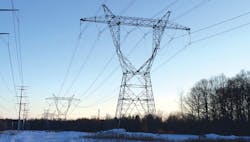
Lattice-steel towers and a single-circuit extra-high-voltage transmission line were built for a planned nuclear plant nearly four decades ago. Today these structures are empowering a critical stretch of electrical transmission infrastructure capable of supporting up to 5000 MW of new wind generation in the Thumb region of Michigan, U.S.
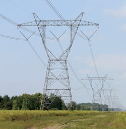
By turning single-circuit 765-kV towers into double-circuit 345-kV towers — a first-of-its-kind conversion — ITC could, creatively, reclaim existing right-of-way, foundations, structures and conductor.
The result eliminated the need to acquire new easements, drill and pour new foundations, erect new structures and string new conductor. It also eliminated the need to demolish existing infrastructure. Reusing conductor from the single-circuit, quad-bundle design for the double-circuit, twin-bundle configuration resulted in increased efficiency.
The decision to retrofit and upgrade existing assets shaved off months from the project schedule and saved millions of dollars. This conversion is one that can provide inspiration as utilities look for unique ways to upgrade their systems to support new generation from renewable resources.
Thinking Ahead
In 1979, a new transmission line was designed and built for 765-kV operation south of the Greenwood Energy Center near Avoca, Michigan. At the time, a new nuclear power plant was planned to be built adjacent to the existing oil-fired plant. However, load-growth projections began to diminish, and ultimately, market conditions did not justify building the new power plant. Instead, the transmission line was operated at 345 kV, eventually interconnecting with an existing 345-kV transmission line to the south — from the Belle River power plant in St. Clair County to the Pontiac substation in Pontiac.
In 2010, during the planning stages of the 140-mile (225-km) Thumb Loop Project — a multi-value project of the Midcontinent Independent System Operator consisting of a double-circuit 345-kV transmission line in the Thumb region of Michigan — ITC identified the need for a new 345-kV interconnection. The existing corridor would need to be upgraded from one single-circuit 345-kV transmission line to two double-circuit 345-kV transmission lines.
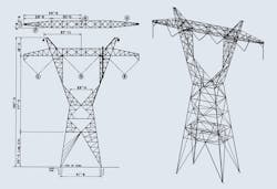
During the routing process, ITC engaged its engineering partner for the project, Burns & McDonnell, to perform a feasibility study on transforming a portion of the existing transmission line — as well as the towers supporting it — from single circuit to double circuit. The proposed reconfiguration would involve converting the existing type 7A lattice-steel tangent towers from a single-circuit 765-kV configuration to a double-circuit 345-kV configuration. The existing quad-bundle 1431-kcmil 45/7 aluminum conductor steel-reinforced (ACSR) Bobolink conductor would be reused in a twin-bundle configuration.
Structural Evaluation
ITC provided the original structure loading and steel fabrication drawings for use in the structural evaluation. The type 7A towers were designed in 1973 to a set of loading criteria that differed from ITC’s current requirements. During structural evaluation, the type 7A towers were analyzed using the current criteria. The towers would need to meet or exceed the latest statutory requirements and industry-standard loading criteria.
Further, the original design of the type 7A towers made use of construction attachment load points. The significance of these load points cannot be overstated. These points and their corresponding attachment plates were used in the initial construction and stringing of the transmission line. More specifically, each of these points was designed to support the full vertical load from one phase. The proposed modifications would require use of these attachment plates, in addition to the existing insulator assembly attachment points.
ITC also provided Method 4 PLS-TOWER models of the type 7A towers and a PLS-CADD model of the existing transmission line, complete with light detection and ranging (LiDAR) survey data. After reviewing the Method 4 PLS-TOWER models for conformance with the fabrication drawings, connection detail and consistency with industry modeling practices, the PLS-TOWER models were incorporated into the PLS-CADD model at each tower location.
Tower location, orientation and position were compared visually against the LiDAR survey data and adjusted as necessary to reflect actual conditions. The structural capacity of each tower was assessed individually with site-specific loads resulting from actual loading conditions in the proposed configuration using PLS-CADD and PLS-TOWER. None of the 15 towers were found to be overstressed in the proposed configuration when analyzed using the current structure design-loading criteria.
In addition to the superstructure, the capacity of the existing tower foundations was an important consideration in the overall structural evaluation. Because the original foundation design reactions and depths were unknown, a simulated design scenario was developed. Foundation reactions representative of the original design loads were generated in PLS-TOWER. These representative reactions were compared to the greatest site-specific foundation reactions in PLS-CADD resulting from the proposed loading conditions on the 15 towers proposed for modification. The site-specific foundation reactions from the proposed modifications using the latest ITC structure design-loading criteria were significantly less than the reactions representative of the original design.
Electrical Evaluation
Aside from the structural feasibility of the proposed modifications, the electrical performance of the modified tower configuration would have to prove to be acceptable, as well. The physical dimensions of the new tower configuration would largely determine the electrical characteristics. Additionally, insulation levels would need to be sufficient enough for the line to continue operating with a high degree of reliability.
An electrical evaluation was performed concurrent with the structural evaluation and included the following:
• A review of clearance values with respect to ground clearances, structure clearances, working clearances, power frequency, switching surge and the expected outage rate
• A review of lightning protection, including calculation of shielding angle and backflash
• A review of the electromagnetic field (EMF), including calculation of conductor surface gradient, corona losses and field strength.
The existing transmission line had sufficient clearance to ground in its existing state. However, in the proposed configuration, clearance to ground would be improved. Replacing the existing 765-kV insulator assemblies with 345-kV insulator assemblies and reconfiguring the transmission line in a horizontal twin-bundle configuration raised the relative conductor elevation by more than 3.5 ft (1 m).
In the proposed configuration, working clearances would exceed those set by the Occupational Safety and Health Administration of the U.S. Department of Labor. Also, phase-to-phase and conductor-to-structure clearances would exceed requirements. Calculations showed the predicted outage rate was 10 times less than the recommended maximum.
One concern with the proposed configuration was the effect on shielding angle. The existing tower configuration provided a shielding angle of 9.5 degrees, whereas the proposed configuration would leave the outside phases more exposed, providing a shielding angle of 23 degrees. However, when calculated for the new configuration, the back-flashover rate, shielding failure flashover rate and total flashover rate compared favorably to industry recommendations.
The electrical field strength was calculated to be less than 0.8 kV/m on the right-of-way and at the edge of the right-of-way. The magnetic field strength was calculated to be less than 33 mG at the edge of the right-of-way. Audible noise levels did not exceed the project requirements. The maximum conductor voltage gradient was calculated to be less than what would typically produce a low probability of objectionable corona levels.
Step-by-Step Execution
After determining type 7A towers would perform well in a double-circuit 345-kV configuration — both structurally and electrically — the next step required the development of insulator assemblies to accommodate the proposed modifications. The existing V-string insulator assemblies were arranged horizontally and consisted of porcelain insulator bells. Insulator assemblies developed to accommodate the proposed configuration consisted of a combination of ITC standard 345-kV polymer insulators arranged horizontally in an I-string, V-string and W-string fashion, while using the construction attachment points and original insulator attachment points. Conductor blowout and clearances to the edge of the right-of-way were reviewed and found not to exceed project limits.
An analysis of potential line galloping was performed, determining repositioned conductors would not be expected to interfere with other phases or shield wires. Lastly, an aeolian vibration analysis also was completed, verifying the effectiveness of the size and placement of the Stockbridge-type dampers present on the existing transmission line.
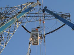
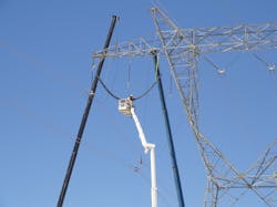
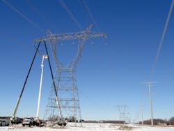
In the summer of 2013, the final design was completed and ITC proceeded with the construction phase of the project. In early 2014, construction crews mobilized to begin implementing the proposed modifications. Overhead cranes were used to suspend the conductor while the existing 765-kV insulator assemblies were removed by a pair of linemen working from a bucket truck.
After the existing 765-kV insulator assemblies were removed, the new 345-kV insulator assemblies were installed. Finally, the existing quad-bundle conductor was separated and clipped into the new 345-kV assemblies in horizontal twin-bundle pairs. This process was repeated phase by phase, tower by tower. In general, a five-person crew averaged approximately one complete tower conversion per day.

Big-Time Benefits
The benefits of the reconfigured line are significant. By having less visually noticeable insulator assemblies, it can be argued the reconfigured transmission line is an aesthetic improvement over the original configuration. The projected cost savings were substantial and realized, in contrast to the construction of another new double-circuit transmission line. This unique conversion enabled savings in the form of reduced labor and equipment costs, compared to the demolition and removal of existing facilities and construction of a new line. Additional savings were realized from reduced material costs typically experienced in procurement of new steel, concrete and aluminum. Efficiently using existing right-of-way also reduced real-estate costs. Furthermore, the overall project schedule was shortened.
Successful Completion
In the spring of 2014, ITC successfully completed the conversion of 15 type 7A lattice-steel tangent towers from a single-circuit 765-kV to a double-circuit 345-kV configuration. The transmission line was placed into service in May 2014 using mostly existing facilities. The success of this project highlights ITC’s focus on operational excellence, improving capacity, efficiency, reliability and safety while delivering unique transmission solutions.
ITC and engineers from Burns & McDonnell believe the performance and success of the conversion, given the project’s unique conditions, is unlikely to be matched. Despite its one-of-a-kind nature, the project provides a great example of innovation and outside-the-box thinking as utilities are forced to upgrade their existing systems in response to market, regulatory and economic forces in today’s transmission industry. ♦
Todd Edwards is a professional engineer, serving as principal project manager for ITC Holdings Corp. in Novi, Michigan, U.S., and has 10 years of experience in high-voltage and extra-high-voltage transmission line design, project execution and management. He holds a BSCE degree from Lawrence Technological University and a MSCE degree from Wayne State University. Edwards is a certified project management professional.
Joe Pattison is a professional engineer with more than eight years of experience in the design of power-delivery projects, ranging from 34.5-kV subtransmission lines up to 345-kV extra-high-voltage transmission lines. He holds a BSCE degree from the University of Kansas and serves as a project manager of transmission line projects for Burns & McDonnell in Kansas City, Missouri, U.S.
About the Author
Todd Edwards
Todd Edwards is a professional engineer, serving as principal project manager for ITC Holdings Corp. in Novi, Michigan, U.S., and has 10 years of experience in high-voltage and extra-high-voltage transmission line design, project execution and management. He holds a BSCE degree from Lawrence Technological University and a MSCE degree from Wayne State University. Edwards is a certified project management professional.
Joe Pattison
Joe Pattison is a professional engineer with more than eight years of experience in the design of power-delivery projects, ranging from 34.5-kV subtransmission lines up to 345-kV extra-high-voltage transmission lines. He holds a BSCE degree from the University of Kansas and serves as a project manager of transmission line projects for Burns & McDonnell in Kansas City, Missouri, U.S.