Asset Replacement: A Step-by-Step Approach
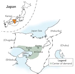
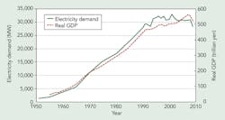
Economic growth in Japan has been sluggish now for almost two decades following the collapse of the country’s economic bubble, and this is expected to continue as Japan transitions from a growth society to a more mature society. The electricity demand in the Kansai area, located in the southern-central region of Japan’s main island, shows a similar trend.
The Kansai Electric Power Co. (KEPC) is the second-largest electric power utility in Japan. The majority of its transmission system was installed in the 1970s and 1980s, which means today, KEPC is facing the enormous challenge of replacing these aged assets. KEPC has designed a master plan to achieve the electric power transmission system it will require by 2030.
Basic Policies
KEPC is confronted with the challenge of replacing aged assets by planning and constructing an optimal electric power system configuration with limited additional investment. This will resolve various issues — including the system’s supply reliability and its operational and maintenance performance — by considering the following key policies that form the basis of the utility’s master plan:
- Supply reliability. An electric power transmission system should prevent a large-scale and prolonged power outage in the case of a fault occurring on the system or one cascaded from another system. It may be possible to improve the reliability of electricity supply with limited incremental costs by increasing the capacity of installed equipment or modifying the configuration simultaneously by replacing aged facilities.
- Cost effectiveness. When replacing an electric power system component, it is necessary to pursue a cost-effective option. For example, it may be possible to reduce the total costs of construction, operation and maintenance by increasing the capacity of an aged component instead of demolishing an adjacent component not scheduled for replacement. It is also necessary to review whether the assets have excess or inadequate capacity, enabling the transition toward a smart system. Also, it may be possible to reduce the total cost of renovating a transmission line that forms a loop system by reinforcing, in advance, the other interconnecting lines comprising the loops, thereby removing the need for temporary transmission facilities.
- Flexibility. Electricity transmission systems should have the capacity and flexibility to meet uncertainties in electricity demand. For example, adequate capacity of the transmission lines enables the availability of electricity supplies to potential customers without undue delay.
- Operation and maintenance performance. Assets installed on transmission systems are designed to be in operation for long periods. To ensure optimal performance, these components should meet all potential operation and maintenance needs, including the ease of de-energization for maintenance work.
- New technologies. When renovating facilities, it is a good idea to add value by adopting state-of-the-art technologies that improve the reliability of supply and optimize the transmission system.
Reliability Improvement
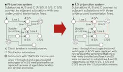
The current KEPC system design standard used in large cities is a pi-junction system, whereby 77/6-kV distribution substations are supplied by 154/77-kV primary substations, each interconnected by two 77-kV underground cables. Although this design standard satisfies the utility’s N-1 contingency criteria, this level of supply reliability is now considered to be relatively low for city centers as there can be a momentary loss of supply in the event of a fault on one of the two 77-kV underground cables.
Therefore, when the utility was faced with the need to replace aged assets (gas-insulated switchgear and 77-kV cables), KEPC decided to design 1.5 pi-junction systems, whereby each 77/6-kV distribution substation is connected to adjacent substations by three 77-kV underground cables. This enhanced the supply reliability, as now there is no loss of supply in the event of a 77-kV underground cable fault.
This example of simultaneously improving supply reliability when replacing aged assets can be used as a milestone for similar situations.
Overhead Transmission Lines
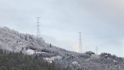
Two existing 154-kV double-circuit overhead transmission lines, both of which are longer than 100 km (62 miles), supply electricity from hydropower plants located in remote areas to the main load centers in the Kansai area. More than 80 years old, these transmission lines had decrepitude issues and had become a huge maintenance burden in terms of cost and manpower requirements because of low ground clearance. In some sections of the lines, it was difficult to trim trees to secure the required safety clearance between the trees and overhead line conductors because of opposition from the forestry industry.
Since the two 154-kV transmission lines are routed across a valley with a separation of several hundred meters, consideration was given to integrating the two lines by building new quadruple-circuit transmission towers that would accommodate both circuits, enabling a significant reduction in the maintenance costs.
The discounted cash-flow analysis showed that construction of a new transmission line complete with quadruple-circuit transmission towers had a cost-benefit advantage when compared with the maintenance of the two existing double-circuit transmission lines. Currently, the KEPC transmission line team is constructing the new quadruple-circuit transmission towers to accommodate the two existing 154-kV circuits.
Distribution Substation Transformers
The KEPC transmission system comprises 850 distribution substations that require, or will require, the replacement of deteriorating aged assets. When the replacement of equipment is under consideration, the needs of the transmission system are examined in terms of the required installed transformer capacity. In general, increasing transformer capacity and decreasing the number of units installed reduces the total replacement costs.
Also, the reduction in the in-service expenditure on maintenance more than offsets the increased capital cost of larger-capacity transformers. However, reducing the number of transformers installed can make it more difficult to obtain de-energization for transformer maintenance work and to minimize the number of customers without supply in the event of an electrical fault. KEPC recently installed a distribution automation system, which has enhanced the switching capability and overcome these potential faults.
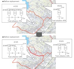
KEPC then started to rationalize the number and capacity of distribution substation transformers by examining the area and number of customers supplied by each distribution substation. For example, instead of replacing an aging 10-MVA, 77/6.6-kV transformer in a distribution substation equipped with three transformers, KEPC decided to install a second 20-MVA, 77/6.6-kV transformer in the adjacent distribution substation. This was made possible by reconfiguring the operating conditions of the existing 6.6 kV to facilitate the transfer of load between the two distribution substations. This change in system design policy, in this particular example, reduced the utilization factors at both substations, thus effectively reducing system losses.
The utility is now using this rationalization of transformer numbers and capacity across its entire distribution network. Each section of the network has different design features, so detailed consideration is given to each project. In addition to improvements in supply reliability, by 2010, the KEPC design team had reduced the number of transformers in the scheduled replacement program from 53 units to 47 units while increasing the installed transformer capacity by 128 MVA. This will enable the utility to accommodate future increased demand while benefiting from the cost savings attributable to the reduction in its transformer population.
Master Plan Results
A large number of KEPC’s electric transmission facilities were constructed during Japan’s economic boom in the 1970s and 1980s. Because of the deterioration of assets, and assets nearing the end of their service life, replacement is planned in the near future. It is important to consider the following issues for each asset replacement project:
- Supply reliability and economic efficiency with simultaneous improvement
- System design flexibility to cater for uncertainties in electricity demand
- Simplification of all operation and maintenance issues
- The use of state-of-the-art technologies to add value to the transmission system.
Based on the master plan approach to electricity transmission system, KEPC has achieved three key objectives:
- Improved the supply reliability of distribution substations in city centers
- Optimized the design of overhead transmission lines
- Standardized the megavolt-ampere ratings of distribution substation transformers.
Junichi Nagahara ([email protected]) received a MSEE degree from the University of Tokyo in 1997. He has worked for Kansai Electric Power Co. for 16 years, mainly with regard to system planning. Nagahara is temporarily assigned to work for the Federation of Electric Power Companies of Japan as deputy manager, and is responding to the central government’s deregulation of the electric power industry as an industry representative. He is a member of the IEE Japan and CIGRÉ.
Koji Nishida ([email protected]) has a master’s degree in precision engineering from Kyoto University and a MBA degree from the University of North Carolina. He has 11 years of experience in overhead line design and transmission planning as well as budget planning and control. Currently, Koji is the assistant manager in the maintenance service office at the Kansai Electric Power Co.
Company mentioned:
Kansai Electric Power Co. | www.kepco.co.jp
