Evergy Stabilizes Damaged Tower
Steel poles and lattice towers historically were thought to be low-maintenance assets that would perform as designed for 50-plus years with little issue. Utility engineering and operations and maintenance professionals are introducing more structurally focused elements to various routine inspection programs, particularly on older lines with aging infrastructure. While conducting a routine patrol, Evergy encountered significant damage to a tower on its high-voltage Clinton-Stilwell transmission line.
At the time, a significant construction project was occurring on the other major line serving the area, meaning a tower failure would result in a prolonged outage for the city of Clinton, Missouri, U.S., and the surrounding area. This situation, coupled with the location of the asset in a very difficult-to- access floodplain meant Evergy’s options were limited. Restoring this tower as expeditiously as possible would involve a unique and complex solution.
Aging Infrastructure
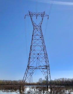
Originally constructed in 1959, the Clinton-Stilwell line consists of primarily wood H-frame construction and bundled conductor. In 1977, the Corps of Engineers requested the line be modified to accommodate the Harry S. Truman Dam and Reservoir near Warsaw, Missouri. The portion of line within the Truman Reservoir floodplain, 10 spans totaling 1.8 miles (2.9 km), was rebuilt to lattice towers ranging from 115 ft to 148 ft (35 m to 45 m) in height. The towers were constructed on drilled pier foundations, ranging from 32 ft to 42 ft (9.8 m to 12.8 m) in depth, with 1-ft to 12-ft (0.3-m to 3.6-m) reveals. These reveal heights do not keep the structures above flood-stage water levels that makes them vulnerable to damage from floating debris in flood events.
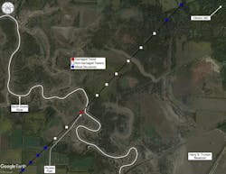
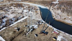
During a routine aerial inspection in March 2021, Evergy maintenance personnel discovered damage to tower 58, located 2.5 miles (4 km) southwest of Clinton, Missouri, and only 165 ft (50 m) southwest of the South Grand River. During the inspection, it was discovered flood debris appeared to have contacted the lattice tower. Evergy transmission engineering was immediately notified of the damage. Because of the elevated water levels in the floodplain, air boat was the only feasible means of access. The next day, Evergy transmission engineering and maintenance personnel accessed the structure to make an on-site assessment. While on-site, the floodwater level was approximately 10 ft (3 m) above natural grade, just over the top of concrete of the drilled pier foundations. The assessment found tension and compression members were visually bent, bolts were missing and the tower was noticeably leaning. The ahead and back towers also were accessed for a brief assessment, but no major damage was noticeable.
Responding To A Crisis
Evergy immediately contacted Exo Group LLC, with whom it had a working relationship from previous projects. From the photos and existing lattice tower drawings, Exo conducted a preliminary assessment of the damage prior to coming on-site and recommended complete structure replacement. Because of the engineering and material lead times as well as the outage constraints, Evergy would not be able to replace the structure for at least nine to 12 months. Temporary stabilization of the structure would be required to prevent a cascading failure and allow the line to stay in service until the complete structure replacement was possible.
The existing line did not have failure containment structures installed, and the closest dead-end structures were approximately 4 miles (6.4 km) ahead and back of the damaged lattice tower. It was critical to avoid extended outages on the line because of ongoing rebuild projects that were contingent on this line supporting the area’s load demand.
While initiating Exo’s temporary stabilization plan, Evergy evaluated contingency options for immediate restoration in case of a failure event. The first temporary option considered was to install multiple direct-embed monopole steel dead-end structures, each supporting a single conductor or shield wire in a shoo-fly-type configuration along the span to maintain ground clearances while minimizing the load on individual poles. These steel poles were readily available in Evergy stock, and it was determined they could support light to medium ice and wind load cases. However, because of the water levels and poor soil conditions, installing direct-embedded poles was not a practical option.
Evergy contacted multiple lattice tower vendors to determine if a like-for-like structure could be fabricated. Because of the condition of the existing lattice tower drawings, it would take four to six weeks to update the drawings to current drafting standards and approximately 18 to 20 weeks to fabricate the new lattice tower. These lead times would not allow much schedule relief from a new tubular steel structure being designed and fabricated. Additionally, a major concern was potentially damaging the existing dilled pier foundations during the removal of the damaged lattice tower, causing uncertainty around the connection to the new lattice tower.
Evergy began discussions with the Corps of Engineers, who oversees the federally owned land leased to the Missouri Department of Conservation. The access route, matting specifications and restoration all were concerns for the Corps. Multiple access routes were proposed until an acceptable route, which had minimal tree removal and ground disturbance, was approved. Only a construction license was required, resulting in avoiding extended lead times to obtain additional permits. Evergy and the Corps maintained constant communication throughout the process, which aided in gaining an understanding of when the reservoir water level would drop to natural grade, so the mat road could be installed.
Gathering Data
A drone inspection was carried out to capture photographic data — to know the extent of the damage and use photogrammetry techniques to develop accurate models of the member and connection details — so a stabilization design solution could be developed. This model would provide accuracy to one-eighth of an inch (3.175 mm). Based on this inspection, the failure root cause and secondary failures were assessed. Reservoir records indicate the full pool elevation was exceeded in March 2021.
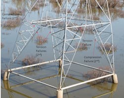
The towers were modeled in PLS-TOWER to assess the overall load impacts to the line if the damaged tower failed. Tower 58 was modeled using the as deflected and damaged condition. The design of the tower uses the concept of tension-only members. Used on many older tower designs, this concept provides a lighter-weight structure, but the design requires horizontal members to resist the compression loads from the shear loads that flow down through tension-only members in the tower.
The tension-only cross bracing also provides bracing support for the main leg-bracing members. The failure occurred on the diagonal tension-only members by shearing the connection bolts followed by the compression failure of the horizontal member. After losing the support of these members, the tower lost the main support to transfer shear to the foundation and the lowest tower leg extension panel subsequently deflected laterally and torsionally. The main approach to stabilizing the tower was to focus on reestablishing the broken load paths because of failures.
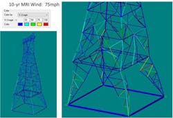
Model geometry stabilizing techniques were applied and loading conditions were based on a mean recurrent interval (MRI) of 10 years, simulating a temporary condition for stabilizing the tower during the replacement period. A load case was developed to simulate a 75-mph (121-km per hour) wind condition based on the MRI for the site location using ASCE 7 Risk Category I. The results indicated overstressed members; however, the main legs were not overstressed. It is important to note the existing tower deflection undoubtably induced stress because of the deflection strain, and this existing stress (prestress) is not accounted for in the model.
A subsequent analysis was performed by which a wind load was incremented by 10 mph (16 km per hour) until the tower was shown to be overstressed by a critical main leg member. This approach produced a limiting wind speed of 30 mph (48 km per hour), which the tower had the capacity to withstand. Any greater wind speed risked a partial or full collapse prior to stabilization.
Additional assessments were made using PLS-CADD to determine the likelihood of a longitudinal or transverse cascade failure event, which would impact the adjacent structures. Longitudinal loading was developed using the methods described in ASCE-74 and applied to the adjacent structures to evaluate the likelihood of the propagation of a cascade failure if Tower 58 were to fail prior to stabilization. It was determined the adjacent towers, which were of the same design capacity but different heights, had a longitudinal capacity meeting the recommendations of ASCE-74. It was not a guaranteed there would be no damage or
further failure propagation, but it did provide some assurances there was a high likelihood any failure would be arrested, minimizing the impacts to the remaining transmission line.
Stabilizing The Tower
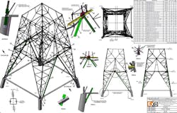
A series of step-by-step operations to stabilize the tower was developed to restore the main load-carrying members and give additional support to the existing members that provide main leg bracing as well as further reinforce the area that had failed. A key aspect of the stabilization was not to disturb the existing members by leaving them in place to provide some stiffness to the tower within the rejoin of failure. It was challenging to determine the best approach to install new stabilizing members without the removal of existing connection bolts and still provide connections to these new members at joints for adequate load transfer.
The main leg diagonal stabilization members were designed as 5x5x5/16 double angles assuming no intermediate bracing. The main horizontal member was a 5x5x1/2 single angle connected to existing open holes on the main legs of the tower. The plan to install these members consisted of a step approach, so the stabilization would not induce additional load onto the already critically loaded leg members.
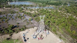
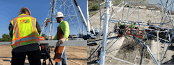
While the 3-D photogrammetry aided in determining the required material to brace the tower, the exact geometry of many of the bolt-hole locations could only be determined with field measurements. A mobile fabrication operation was set up next to the tower to facilitate precise hole locations that would fit the tower in its deformed state. Once complete, the parts were hoisted to the appropriate location on the structure and installed. In total, 40 pieces of steel plate and angle, weighing roughly 5000 lb (2268 kg), were used to brace the tower.
The effort to fabricate and install the bracing elements required for stabilization took three days and 11 crew members. Despite a six-week delayed start date because of unprecedented rainfall in June 2021, the project was completed safely and within the needed time frame.
A Lasting Solution
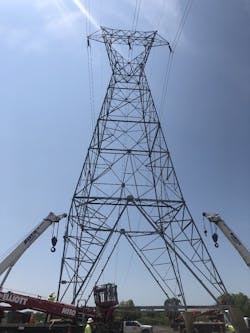
For the tower replacement, Evergy engaged Valmont Industries Inc. to design a new PyraMAX tubular structure. The PyraMAX provides resiliency to possible flood debris damage in the future while allowing for expediated framing because of the tubular nature of the structure, not requiring the large quantity of
individual elements of a lattice tower structure.

The structure design includes an impact load case replicating a 2000-lb (907-kg) piece of debris floating at a rate of 10 mph, which through consultation with the Corps of Engineers was found to be the typical maximum flood-stage water flow. Using the 2012 FEMA P-259 Engineering Principles and Practices (equation 4-11) and ASCE 7-10 Minimum Design Loads for Buildings and Other Structures (equation C5-3), the impact load was calculated and incorporated into the structure design.
The structure was designed for the existing loading conditions for a 150-year return period as well as more stringent future conditions of a full line rebuild with a 200-year return. The design also includes 0.15 inch (3.81 mm) of sacrificial steel based on a 50-year exposure to corrosive flood waters using 0.003 inch (0.08 mm) of loss per year, per NHI-10-016 section 6.2.3 publication of the Federal Highway Administration’s (FHWA’s) National Highway Institute (NHI). Evergy also had Valmont prepare designs for additional heights of the structure should any of the adjacent lattice towers also experience flood damage in the future, reducing the lead time for a complete structure replacement.
The geotechnical assessment was performed showing subsurface conditions consisting of lean clay and clayey sand to a depth of 17 ft (5.18 m), with sandstone, shale and limestone for the duration of the boring until it was terminated at 50 ft (15 m). With the wet conditions, drilled pier foundations were not considered an option because of the constructability of the four-legged structure and potential for losing an excavation. Vibratory caissons also were not considered because of the shallow bedrock preventing them from reaching the depths required for the full skin-resistance capacity.
Evergy contracted Crux Subsurface Inc. and Quanta Subsurface for the design and construction of a micropile foundation system that uses a steel riser and cap. To minimize the possibility of flood debris contacting the structure, the utility evaluated the reservoir elevations for the available 13-year duration compiled by the United States Geological Survey (USGS). The water elevation was found to exceed a height of 725-ft (221 m) mean sea level (MSL) approximately 5% of the time. This top-of-foundation elevation would yield a 15-ft (4.5-m) reveal, 5 ft (1.5 m) higher than the existing drilled pier concrete foundation.

The micropile foundation also would account for the previously derived impact load contacting it and the sacrificial loss of steel per FHWA, as well as a 7-ft (2.1-m) scour depth as recommended by FHWA HIF-12-003 and the lateral load from flood water pressure on the riser. The micropile geometry for each leg includes four piles on a 66-inch (1676-mm) array diameter with a five-degree batter and a minimum embedment/bond length of 26.5 ft (8 m). The riser and cap include a 76-inch (1930-mm) outside diameter bottom cap for the micropile connection and a 52-inch (1321-mm) outside diameter top cap for the structure baseplate connection, with a 12-inch (305-mm) inside diameter to tighten the interior anchor bolts.
Evergy completed the micropile installation in January 2022, with the total construction duration only lasting approximately two weeks. The PyraMAX structure was installed, and the existing conductors and shield wires transferred in February 2022. During the micropile installation, soil conditions were found to be consistent with the geotech data, resulting in the estimated micropile depths being accurate. Following the construction, the mat road was removed and the area restored back to its original condition.
Future Grid Resiliency
The assessment and stabilization portion of this project had an overall positive outcome. Using emerging technologies, such as drone data capture and 3-D photogrammetry modeling, the Evergy and Exo teams were able to quickly analyze the damage to the tower, the associated risks of failure as a result of the damage and the optimal solution to stabilize the tower for any duration needed until a new structure could be installed.
The field work was executed safely and without issue. The nearby area was spared of what would most certainly have been an extended outage had Tower 58 failed. The new PyraMAX structure will harden the system from future flooding events and provide reliable power delivery for Evergy customers long into the future.
Michael Miller ([email protected]) is the VP of Technical Services at Exo. He has 33 of experience as a civil engineer in the electrical transmission structures industry designing, analyzing and testing critical infrastructure. He has BS and MS degrees in Civil Engineering from Portland State University and is licensed as a professional Civil Engineer in over 20 US States and several Canadian provinces. He is a member of IEEE, CIGRE and a Fellow at ASCE and ASCE/SEI.
Grant Leaverton ([email protected]) works as a Senior Account Manager for Exo helping clients solve structural integrity issues with critical
transmission and substation assets. He has been in the utility industry for 11 years and holds a B.S. in Industrial Engineering from Texas A&M University and an MBA from Southern Methodist University.
Clint Wilmes ([email protected]), P.E., is a project manager at Evergy in the large transmission and substation construction group. He was formerly a senior transmission line engineer at Evergy for three years. Prior to Evergy, he worked at POWER Engineers Inc. for seven years. Wilmes earned his BSCE and MSCE degrees from the Missouri University of Science & Technology and is a registered professional engineer. His responsibilities in the engineering group at Evergy include overseeing transmission line capital projects ranging from 69 kV to 345 kV.
For More Information
Crux Subsurface | www.cruxsub.com
Quanta Subsurface | https://quantasubsurface.com
Valmont | http://www.valmont.com
About the Author
Grant Leaverton
Grant Leaverton works as a Senior Account Manager for Exo helping clients solve structural integrity issues with critical transmission and substation assets. He has been in the utility industry for 11 years and holds a B.S. in Industrial Engineering from Texas A&M University and an MBA from Southern Methodist University.
Michael D. Miller
Michael D. Miller is the VP of Technical Services at Exo. He has 33 of experience as a civil engineer in the electrical transmission structures industry designing, analyzing and testing critical infrastructure. He has BS and MS degrees in Civil Engineering from Portland State University and is licensed as a professional Civil Engineer in over 20 US States and several Canadian provinces. He is a member of IEEE, CIGRE and a Fellow at ASCE and ASCE/SEI.
Clint Wilmes
Clint Wilmes ([email protected]), P.E., is a project manager at Evergy in the large transmission and substation construction group. He was formerly a senior transmission line engineer at Evergy, formerly KCP&L, for three years. Prior to Evergy, he worked at POWER Engineers Inc. for seven years. Wilmes earned his BSCE and MSCE degrees from the Missouri University of Science & Technology and is a registered professional engineer. His responsibilities in the engineering group at Evergy include overseeing transmission line capital projects ranging from 69 kV to 345 kV and assisting the maintenance group with day-to-day tasks.