American Electric Power (AEP) recently developed base shoe and standoff anchor bolt designs for its 765-kV lattice tower family. Developing a design process proved challenging, as a ready-to-use methodology could not be identified. Instead, a variety of approaches were identified from industry publications that were contradictory and yielded significantly different results. This required AEP to develop their own approach for this unique type of base plate.
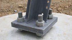
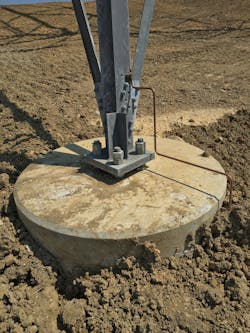
Achieving economic construction of lattice towers requires the ability to connect the superstructure to a variety of foundation types. That led AEP to undertake the design of base shoes for its 765kV tower family that could be utilized for transferring loads to both concrete pier and micropile capped foundations. A design using standoff or double nut anchor bolts was selected. This provided the flexibility to adjust the stub setting and avoids water infiltration, corrosion, and inspection issues that can occur when base plates are grouted after construction.
The design of anchor-bolted base plates for self-supporting transmission towers is unique. When compared to other structures such as moment frames, tubular steel transmission poles, or highway signs, lattice towers produce large axial loads as opposed to large bending moments. The result is similar design loads for all anchor bolts in the group and provides less redundancy when compared to anchor bolt groups with large overturning moments where only a few bolts are subjected to the maximum design loads. A review of available literature from the American Society of Civil Engineers (ASCE), American Institute of Steel Construction (AISC), and American Association of State Highway and Transportation Officials (AASHTO) resulted in a variety of approaches for base plate and anchor bolt design that offered little consistency.
Anchor Bolt Bending
A significant design decision was whether the effects of flexure on the anchor bolts should be considered when determining the required quantity and layout. Most design standards and guidelines from AASHTO, ASCE and AISC allow flexure in the anchor bolt to be ignored if the distance between the top of concrete and the bottom of the base plate is less than or equal to two anchor bolt diameters.
The recommendation is based on full scale base plate and anchor bolt tests where the applied normal stress in the anchor bolt due to bending is less than ten percent of the total axial stress. This is a common stress condition for anchor bolt groups subjected to large overturning moments and small shear loads but not a typical stress distribution for lattice towers. For the lattice towers in this study, the stress due to bending accounted for approximately fifty percent of the total normal stress. Given the uncertainty of anchor bolt behavior for this condition of combined loads it was deemed prudent to include anchor bolt bending in the design approach.
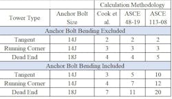
Only three references were identified that provided a complete documented method for including anchor bolt bending: ASCE 113-08, ASCE 48-19 and a paper by Cook, Pravett, and McBride for the Florida Department of Transportation. All three methods assume the anchor bolt deforms in double curvature. However, the assumptions for the flexural length of the anchor bolt and the amount of fixity at either end were all different. The methods used different values for allowable bending stress of the bolt and whether the elastic or plastic section modulus was used when calculating bending capacity.
These three methods were used to calculate the required number of anchor bolts for a tangent, running corner and dead end structure from the 765kV lattice family and compared to the requirements if bending was ignored. Including bending resulted in an increase of anchor bolt quantity by as little as 25%, or as much as 250%. The method proposed by Cook et al. was selected as it required only a moderate increase in the required number of anchor bolts and has been shown to provide good comparisons with experimental results.
Finite Element Analysis
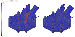
A nonlinear Finite Element (FE) model was created for each base plate to verify the design approach. The impact that plate flexibility has on stress distribution throughout the stub and the distribution of anchor bolt forces was of particular interest. The base plates were modeled as elasto-plastic solids in Autodesk Inventor Nastran. Each model included the base plate, stub angle, stiffeners, anchor bolts and leg diagonals.
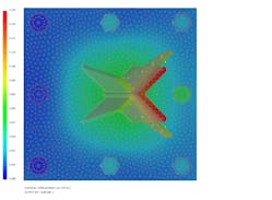
FE results for the more heavily loaded running corner and deadend towers showed additional stresses in the assembly than were originally anticipated, specifically around the toe of the stub and stiffeners. Under load, the base plate begins to deform into a bowl. The stub and stiffeners resist the deformation by concentrating forces at the tips where the change in deflected shape is most pronounced. The stress concentrations in these “hotspot” locations are impacted by the thickness of the base plate. Stresses decrease in magnitude with the increase in plate thickness and rigidity.
A review of several variations of FE models (above) led to the conclusion that the ratio of the distance from the anchor bolt to the bend line, c, divided by the plate thickness, t, should be a maximum of 3.25 for this tower family to mitigate additional stresses caused by plate deformation.
The FE models were also used to calculate the anchor bolt forces for the maximum compression load case, which was controlling for anchor bolt and base plate design. For the three-bolt and four-bolt designs, these forces were found to be within five percent of the forces calculated using a simplified a rigid base plate assumption. The resulting centroid of the anchor bolt forces act within approximately five percent of the centroid of the weldment assembly.
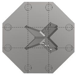
For designs that require more than four anchor bolts, however, the FE study did not always agree with the simplified rigid base plate approach. The rigid baseplate model is only appropriate when anchor bolts are placed equally into four quadrants around the welded stub assembly, and concentrically to the centroid of the load. The original base shoe design for the deadend tower placed eight anchor bolts in a square bolt pattern, one in each corner, and one at the midpoint of each face. In this arrangement, the anchor bolts located on the corners of the base plate were not engaged. Ninety five percent of the vertical reaction was collected by the four side bolts. The four corner bolts were essentially unloaded indicating that flexibility of the base plate matters.
The bolts on the sides of the base plate are closer to the stiffened center core. The relative cantilever stiffness of the base plate between the bolts and the stiffened core is greater for the side bolts compared to those at the corners. Even a marginal difference in cantilever distance results in a large difference in stiffness. As a simple analogy, the stiffness of a simple cantilever beam subjected to a tip load is inversely proportional to the length of the cantilever cubed. A 10% increase in cantilever length results in a 25% decrease in stiffness.
Per these findings, the eight-bolt base shoe was redesigned to locate the eight anchor bolts equally in each quadrant and concentrically around the centroid of the welded assembly. A FE analysis of the adjusted design found that the rigid base plate assumption would predict anchor bolt axial forces within about 10%. Additionally, the location of resultant leg forces lands within approximately ten percent from the centroid of the welded base shoe assembly. These results indicate that all anchor bolts should be equally distanced from the stiffened center of the plate to use rigid plate assumptions when calculating axial design forces.
For the specific eight-bolt geometry included in this study, it was also found that applying a load factor of approximately 10% to the calculated anchor bolt forces is prudent to account for the remaining uncertainty.
Constructability Considerations
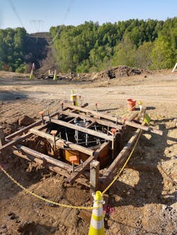
Past experience has shown that the best technical solution is worthless if the design proves to be a challenge to construct. For these designs, anchor bolts were limited to circular patterns to decrease the chances of misalignment in the field. Also, anchor bolts were located such that the centroid of the anchor bolt circle coincided with the centroid of the built-up stub and stiffener weldment, the center of the base plate and the center of the drilled shaft.
Leg diagonal geometry needs to be considered when laying out the bolt patterns to avoid interference with the anchor bolt. Details such as whether the leg diagonal mounts to the inside or outside of the stub can be important. A simple plan view drawing may suffice, but 3-D modeling is recommended if bolts are located below the leg diagonals.
Conclusion of Study
This study allowed AEP to develop a generalized base shoe and anchor bolt design methodology that is consistent with current approaches and incorporates the findings of finite element analysis. Anchor bolt flexure was included in the final design approach, even though the standoff distance between the concrete and base plate was kept below the two-diameter limit.
Finite element analysis was used to refine the design approach and revealed that assuming a rigid base plate for calculating anchor bolt forces is effective for designs with four or fewer anchor bolts. For more heavily loaded towers, the rigid base plate assumption can still be utilized with some simple to follow rules for anchor bolt placement and minimum base plate thicknesses.
There is a gap in full-scale testing of base plates and anchor bolts for lattice towers. Existing test data is limited and does not consider cases where the magnitude of axial stress due to bending approaches fifty percent of the total axial stress in the bolt. Additional testing is required for determining the most appropriate model for including the effects of anchor bolt bending in base plates of this type.
