Are Guyed Towers Cost Effective?

For decades, self-supporting towers have been predominant in extra-high voltage (EHV) overhead transmission line design. Four recent projects have augmented their tower families with guyed alternatives, and these projects provide an opportunity for direct comparisons between self-supported and guyed designs.
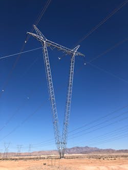
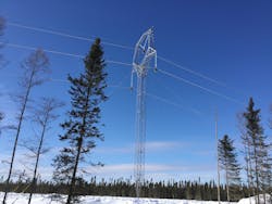
Self-supporting towers support themselves via four legs attached to foundations. The applied forces are transmitted by truss action from the point of application throughout the structure to the foundations. Guyed structures use steel cables attached to anchors to keep the central lattice mast(s) in compression while the guys and anchors remain in tension. This system uses the most optimal application of the structural elements — cable in tension, mast in compression. This in turn makes guyed structures easier to erect and less costly but requires a larger physical footprint.
The selected projects used for comparisons were 500 kV AC projects located throughout the United States. Two of the projects had ice loading, and two of them were in areas where no ice loading was required. All four projects incorporated failure containment for tangent structure designs and all four used a triple bundle conductor arrangement. Two of the projects used identical loading between the guyed and self-supported structures, while the other two projects had similar loading.
The self-supporting structures of the fourth project did not incorporate differential leg extensions as the other projects did. Rather, its body extensions were designed to be installed on foundations using the same concrete elevations. This is pertinent in structure weight comparisons because towers that do not have to support leg extension differentials are less robust than those that do. The Project 4 self-supporting structure weights are comparatively less than those of the other projects selected for comparison due to this difference in design philosophy.
Structure Weight Comparisons
For a guyed tower, there is an optimum mast size for any given range of heights and set of loading parameters. Any mast length above this range would be in danger of buckling, and any mast length below this range would be overly robust. Hence, guyed structure families are available in a narrower height range than self-supporting structures.
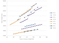
A given height of a self-supporting tower family has four equal leg extensions, and for towers that had multiple heights available via a different combination of body and leg extensions, the lightest configuration was selected. In the chart below, the lines with circles represent the self-supporting structures, and the lines with squares represent the guyed structures.
As expected, the guyed structures are much lighter than their self-supporting counterparts. They ranged in weight from 47% to 75% of the weight of self-supporting structures, depending on project and height. Furthermore, the guyed structures use incrementally less steel than the self-supporting
towers to increase in height, as represented by slopes of each line.
Across all projects, the guyed structures exhibit a linear weight to height relationship, but the slope for the guyed structures is less than that of the self-supporting structures. Three of the projects have self-supporting structures increasing in a generally linear fashion, but with steps. These steps represent an alternative configuration with an additional body extension. The self-supporting structures of Project 4 do not exhibit this behavior.
As previously mentioned, this project did not have differential leg extensions. The additional body extensions of the Project 4 tower family trends linearly, similar to the guyed structures, but at an increased ratio of steel necessary to add height. It is important to note that the guyed structures are only available for an optimum height range and that the self-supporting alternatives are available for a larger height range than shown in the data presented.
The relationships shown are only valid for this limited range of heights. Increasing the height of the guyed structure family would require larger masts, due to mast stability considerations, moving the weight/height line vertically and to the right on the graph, but would increase the amount of steel to height (slope of line) in a fashion similar to that for the other guyed structures represented in the data, albeit with a slightly greater slope.

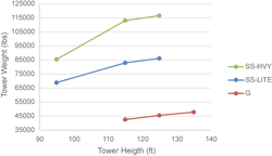
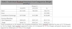
Only Project 4 used a guyed deadend structure as well as self-supporting deadends. This project tower family did not include unequal leg extensions. If it had, one would expect the weights of the self-supporting towers to increase. This project had a light deadend for line angles of less than 40° and a heavy deadend for line angles between 40° and 90°. While the self-supporting and guyed structures only overlap for two height values, it is noteworthy how much less steel is required for the guyed versions.
The difference is perhaps even more striking than that of the tangent case, as guyed structures in the tangent case were on average approximately 65% of the weights of the self-supporting structures, whereas in the deadend case this ratio is approximately 55% for the light and 40% for the heavy deadend.
Structure Cost Comparisons
Foundations for guyed structures consist of a central pedestal that supports the vertical load and is always in compression and four guy anchors that are always in tension due to the guy loading. Foundations for self-supporting structures need to account for uplift and compression loads. Thus, the foundations for guyed structures are generally smaller and easier to install.
Differences in construction tolerances are also noteworthy between the two. Stub setting tolerances for self-supporting towers are on the order of fractions of an inch, as is necessary for the myriad series of connections that make up self-supporting towers. By contrast, guyed structures often utilize precast pedestals, and guy anchor tolerances are on the order of a foot.
In the case of non-precast pedestals, the foundation is still simplified in that the control dimensions are the height, angle, and spacing of supporting pins on the same foundation, rather than the coordination with three other foundations. A single pin supports a single mast delta structure, and two pins support a guyed V-style structure.
Erection of the two types of structures can also differ. Because the guyed structures are significantly lighter than self-supporting towers, they can be picked and placed as a complete assembly. These constructability considerations, in addition to the structure weight, influence the installation costs of the towers.
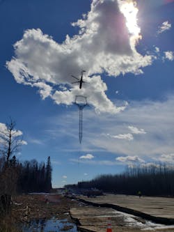
An additional consideration is assembly and construction of the towers. Many of the guyed towers are designed to take advantage of a single tower lift with a heavy haul helicopter. In the case studies, this would apply to Projects 3 and 4 because the practical upper limit for these helicopters is 20,000 lb. While the self-supporting towers can be designed to be installed with a helicopter, they require expensive and complex splices, impacting construction cost.
The first table presents a simplified structure cost comparison. The cost information is semi-empirical — i.e., cost information is derived from actual project information and applied across the four projects. On average across the case studies, the installed cost of guyed tangent structures is approximately 61% of the cost of self-supporting structures. The values given are in year 2020 USD and should only be used for comparative purposes.
The installed cost of the guyed deadend is approximately 80% of that of the light self-supporting deadend and 58% of the heavy self-supporting deadend. An important consideration, however, is the additional right of way and/or guying easements required by guyed deadend structures.
The footprint of the presented 115 ft guyed deadend is a rectangle of 206 ft by 124 ft and taller structures would require additional guy lead length, enlarging this rectangular footprint. Despite their larger footprint, guyed deadends provide construction flexibility. The same structure is used for all line angles and the construction tolerances are less stringent.
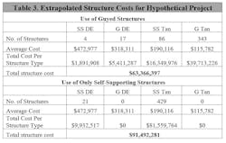
Using the costs from the first two tables, a cost estimate comparison can be prepared for a hypothetical transmission line as presented in the third table. For a 100-mile line and a 1,200-foot average span length, we would expect about 450 structures to be installed. A deadend will be placed every 5 miles, and 80% of site locations allow for guyed structures.
We use the average cost of the presented light and heavy self-supporting deadends, indicating a 50/50 split utilization of each structure, and the average guyed and self-supporting structure costs across the case studies. This scenario is presented against the case of completely self-supporting structures.
Using guyed structures in the hypothetical project results in a 30% reduction in structure costs. It is important to note that 80% of sites were suitable for use of guyed structures, and guyed structures cannot usually be applied throughout a given line. Another important consideration is the guyed structure development cost. Costs for design, detailing, and testing a tower can range in the hundreds of thousands of dollars, and the length of line to spread those costs should be considered in the development of a tower family.
Guyed Structure Performance and Limitations
All of the structure families have tangent tower longitudinal loading capabilities. This is recommended by ASCE MoP 74. A guyed structure has significant advantages in the event of a longitudinal loading event given its inherent flexibility.
Taking one of the projects as an example, the difference in deflection under the project longitudinal event was 6 ft vs. 15 in. for its self-supporting counterpart. This characteristic highlights that a longitudinal failure event will have its energy dissipated more rapidly with the increased structural movement of guyed structures. The more of these “energy dissipators,” the fewer of them will be damaged in triggering events such as storms. Many designers will reduce the use of a deadend tower for failure containment in long tangent runs for this reason on guyed tower lines.
It has been suggested that the guyed tower, particularly the guyed V tower, is the most utilized transmission tower in the world. Its origin dates from the late 1950s when Canadian engineers studied the use of the popular (at the time) Portal tower on uneven terrain.
Installations of the guyed V first appeared in the early 1960s and have been internationally popular ever since in voltages up to 1100 kV. Guyed towers are not appropriate for every project, however, and have limitations, which include:
- Their use requires a footprint that may not be available or approved.
- Many jurisdictional authorities don’t allow guys on lines because of mixed use safety concerns — snowmobiles, ATV’s, motorcycles, etc.
- Agricultural areas are incompatible with guyed structures.
• Guyed structures have been subject to
some notable instances of vandalism.
• Guyed structures require additional
maintenance over time related to guy
inspection and adjustment
This study suggests a resurgence in the use of guyed towers in EHV line design in the United States. The significant cost and performance advantages of guyed towers cannot be overlooked by designers and managers of line projects, though use of guyed towers may be precluded in some cases by property owner or government limitations. Their continued use will only increase industry experience, resulting in further design and construction capabilities of guyed lattice structures.
Jared H. Smith ([email protected]) is a project engineer for overhead transmission lines. His design experience includes all common structure types in voltages up to 500 kV. He has designed new transmission lines and rebuilds of existing lines and conducted as-built analyses of existing lines. He holds a bachelor’s degree in civil engineering from Boise State University and a master’s degree in physics from Colorado State University.
Darel Tracy ([email protected]) is a project manager with expertise in EHV transmission line design projects. He has extensive experience in both utility and consulting engineering environments, and he received both his bachelor’s and master’s degrees in civil engineering from the University of Idaho.
About the Author
Darel Tracy
Darel Tracy ([email protected]) is a senior project manager with POWER Engineers Inc., with considerable experience in both utility and consulting engineering. He specializes in project engineering management of multidisciplinary projects, including right-of-way coordination, public process, transmission, distribution and substation design coordination. His experience includes T&D design as well as familiarity with national, state and local permitting, including National Environmental Policy Act, Bureau of Land Management and U.S. Forest Service coordination. He has extensive experience in public meetings and presentations for city and local permitting agencies.
Jared H. Smith
Jared H. Smith is a project engineer for overhead transmission lines. His design experience includes all common structure types in voltages up to 500 kV. He has designed new transmission lines and rebuilds of existing lines and conducted as-built analyses of existing lines. He holds a bachelor’s degree in civil engineering from Boise State University and a master’s degree in physics from Colorado State University.