Long Span Transmission Structures Go 3D
Never before has the power delivery system needed such a wide variety of structures and towers to meet the needs of transmission grid. Some transmission lines require very long span crossings over rivers and other obstacles. The increased height and heavy loading may make lattice towers and tubular H-frames inefficient designs for these structures.
Innovative tubular 3D (3 dimensional) frame design are an effective solution for developing those tall, long span transmission structures. The 3D configuration significantly increases the structural capability in resisting heavy longitudinal loads due to broken wire or unbalanced wire tensions. While the overall configuration may appear similar to lattice towers, all main members in this type of frame are tubular sections that provide much higher loading capacities.
As the utility industry continues to build a more reliable and more interconnected power grid, we have seen an increased need for more special transmission structures crossing longer spans and carrying heavier loads. This presents a new challenge for structural engineers because neither single tubular poles nor H-frames, even in large sizes, yield efficient or cost-effective designs in these applications. The 3D tubular frame is a new solution integrating advantages of tubular strengths and multiple legs with sub-bracing.
In the United States, tubular 3D transmission frames have been used in limited applications in the past. In many high voltage substations, deadend A-frames are installed but they are not tall. In China, pipe leg lattice towers are used in 1000-kV ultra-high voltage transmission lines replacing angle legs with round tubular members to increase loading capacity. In the US and Japan, pipe leg lattice towers are also used for some telecommunication structures.
The tubular 3D transmission frames developed by Valmont Utility are different structures. The modular configuration is customized for optimum design of structures with various heights, number of circuits, loading conditions and foundation footprints. Frames more than 400 ft. (122m) tall with 80 ft. x 80 ft. (24m x 24m) footprint have been designed and fabricated.
Most frames have long spans crossing rivers or lakes, including angle and dead-end frames with heavy loads in both transverse and longitudinal directions. New types of connections and brace members are designed and validated by both Finite Element Analysis and full-scale load test.
Configuration
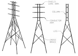
The typical configuration of a double-circuit 3D tubular frame includes upper body and lower body connected at a transition height. The upper body has four vertical tubular columns, tubular conductor arms and shield wire arms. The conductor arms are horizontal, and they are in the middle vertical plane between two front columns and two back columns.
The conductor arms are connected to the four vertical columns with flange joints. Arm(s) for shield wires can be one horizontal arm connected to the top of vertical columns or can be two slanted arms connected to the top of front columns. The lower body has four tubular legs inclined to the vertical axis extending from the transition height down to foundations at the ground line.
The base plate at the bottom of each leg is connected to the anchor bolts in reinforced concrete foundation or to steel caisson foundation. Tubular cross braces are used at various heights to connect two legs in each of the four face planes in lower body.
A 3D tubular frame may look like a lattice tower or pipe leg tower, but the quantity of members is much less which reduces installation labor and erection time. Additionally, the four legs connected with cross braces convert external loading to large axial force and avoid large bending moment at the base.
The customized tubular legs are sized to support the required axial and bending loads. The leg members can be tapered or non-tapered. They not only offer higher capacity resisting axial tension and compression forces, but also have sufficient capacity resisting buckling and bending. Some structures require helicopter installation because access to the site is not available or because the structure height makes crane installation infeasible.
The weight of members in a 3D tubular frame can be controlled in design to accommodate helicopter installation options. The reduced bending moment at the base also reduces foundation size and cost.
Design and Analysis
The design of tubular 3D frames follows the ASCE 48 Standard ‘Design of Steel Transmission Pole Structures’. This standard has established a full set of criteria for tubular members and connection designs, and requires a nonlinear analysis with second order effects. The legs, columns and cross arms are modeled as beam members. The cross braces are modeled as axial force only truss members. The grades and types of steel used for 3D frames are the same as for transmission poles.
Because of the importance and height of a long span structure, usually a higher reliability level is considered by the line designer. The extreme wind load cases should include wind in several directions – transverse, longitudinal and diagonal.
A robust and visual design software is paramount to model and analyze this new type structure. An in-house program for tubular structures has been enhanced to process the increased complexity of tall 3D frames.The goals of design optimization are to minimize bending moments at base of the legs and to minimize total structure cost. Although the common footprint pattern is a square, a rectangle pattern can be more efficient for some frames. There are times when the right of way is smaller than the optimal footprint. It is essential to know upfront if there is a limit to the available space.
The tubular 3D frames are much more rigid than single poles in both transverse and longitudinal directions. Deflections in tubular 3D frames as a percentage of structure height are much smaller. Even under the maximum design load, deflection at top of these frames is typically between 2% and 3% of the structure height.
ANSYS Validation
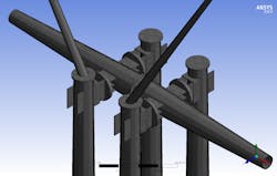
If the design and optimization by in-house software is like ultrasound in a medical checkup, the more sophisticated FEA in ANSYS is like an MRI, which scans and produces more detail and depth into the target areas to make sure nothing is overlooked. ANSYS provides a rich graphics capability that can be used to display analysis results on a very high-resolution graphics workstation.
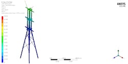
ANSYS computational model solves linear and nonlinear 3D PDEs (i.e. strain displacement, nodal displacement, and stress equations), to determine the deformation, stress, strain, and forces across each node in the solid domain. Accuracy of FEA is in proportion to the degree of mesh refinement in the model. A highly refined mesh is used in this analysis.
The solid mesh contains approximately 15 million hexahedron and tetrahedron elements, with mid-size nodes activated and an inflation of five to 10 layers around the outer walls. The average size of the mesh is 0.1 in. (2.54 mm). All computational studies are performed on a high-end desktop workstation that utilizes 40 cores to handle such huge number of mesh elements.
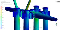
Engineer’s knowledge and experience are important in performing FEA and interpreting the results. Maximum stress in controlling load cases at isolated ‘hot spots’ are higher than the 65 ksi (448 Mpa) minimum yield strength of steel used for pole and arm shafts. Peak stress at isolated ‘hot spots’ somewhat higher than yield strength in highly refined FEA model is not an issue in reality.
The best way to prove it is via full-scale loading test. Except hot spot peak stress, ANSYS results of the static analysis are very close to the results from the in-house design program.
Another motivation for the ANSYS analysis comes from inspection of the static design output. A tubular 3D frame results in long and slender members that are susceptible to Wind Induced Vibration (WIV) due to vortex shedding. It is important early in the design and validation processes of this new product to perform a Computational Fluid Dynamics (CFD) type analysis either to verify that vibration is not an issue or to take steps to mitigate vibration before design is finalized and structure is fabricated. Details of the CFD vibration mode and mitigation analysis are beyond the scope of this paper.
Full Scale Loading Test
To further validate the design, quality and performance of tubular 3D transmission frame, a full-scale loading test was performed. Six load cases were selected by the customer and Valmont engineers for the test: one extreme wind, one deflection limit and four broken wire cases.
The broken wire condition is at one shield wire plus one conductor point or at two conductor points. The transverse and vertical loads were applied at two shield wire points and six conductor points. Longitudinal loads were applied at the shield wire and conductor points where broken wire conditions occur. The wind load on the frame itself was converted into concentrated transverse forces at the top and bottom of the right columns.

The 3D test frame passed 100% loading in all six load cases without failure or permanent deformation in any member or connection. After loading was removed, the structure came back to about 1 in. from the original position. Deflections met customer specified limit and were close to calculated values. After the structure was disassembled, post-test inspection confirmed everything was in good condition.
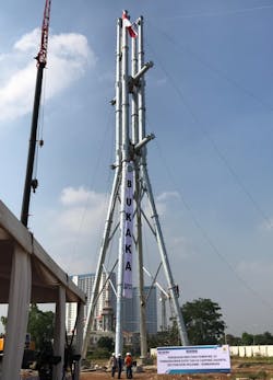
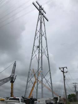
Examples of 3D Frame
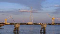
Most tubular 3D frames have been designed and supplied for U.S. customers. Entergy Louisiana’s largest transmission
project in its history was the ‘Lake Charles’ project. The structures are 305 ft. (93 m) to the top with 10 ft. (3 m) tall lightening rod above. The span between the two frames is almost 1500 ft. (457 m). The spread of steel caisson foundations is 48 ft. (14.6 m) in transverse direction and 96 ft. (29.2 m) in longitudinal direction.
Conclusions
- The innovative tubular 3D transmission frame is an effective solution for very tall structures crossing long spans.
- The R&D process and design process of tubular 3D frames have undergone comprehensive static analysis, ANSYS FEA validation and full scale loading test.
- Tubular 3D frames have been successfully installed and put in operation for US and international customers.
William Reisdorff Jr is the vice president of Engineering for Valmont Industries Utility division. He has 36 years of experience in the utility industry and has worked with many utilities and many interesting structures over those years. Reisdorff is a graduate of the University of Nebraska with a bachelor of science degree in Civil
Engineering. In addition, he is a registered Professional Engineer in the state of Nebraska. Reisdorff is a member of the ASCE 48 committee, the ASCE 74
committee, and the NESC sub-committee 5.
Anthony J. Hansen, PE Emeritus, has been married for 46 years to wife May. They have three children and five grandchildren. He graduated from the University of Nebraska with a BSCE. Hansen joined Valmont Industries in 1981 and worked in various capacities in the utility division, the communication engineering department, and the wind energy department. Hansen holdsfour patents and has co-authored two papers. He retired in 2019.
Donghui Yuan is the senior engineering director of North America Transmission in Valmont Utility. He has 28 years of experience designing steel tubular transmission, telecommunication and lighting structures in U.S. and International projects. Donghui has a bachelor’s degree in naval architecture from Shanghai JiaoTong University and a master’s degree in civil engineering from Iowa State University. He is a registered P.E. and certified PMP.
Diaaeldin Mohamed is the senior R&D engineering manager at Valmont Utility. Dr. Mohamed is Valmont’s subject matter expert in finite element analysis, computational fluid dynamics, fluid-structure interaction, and fatigue studies. Dr. Mohamed leads the wind-induced vibration analysis to mitigate the vortex shedding phenomenon in solar trackers, transmission, and substations structures. Dr. Mohamed holds two patents and has co-authored 28 publications. Dr. Mohamed is married and has two children.
About the Author
Anthony J. Hansen
Anthony J. Hansen, PE Emeritus, has been married for 46 years to wife May. They have three children and five grandchildren. He graduated from the University of Nebraska with a BSCE. Hansen joined Valmont Industries in 1981 and worked in various capacities in the utility division, the communication engineering department, and the wind energy department. Hansen holdsfour patents and has co-authored two papers. He retired in 2019.
Donghui Yuan
Donghui Yuan is the senior engineering director of North America Transmission in Valmont Utility. He has 28 years of experience designing steel tubular transmission, telecommunication and lighting structures in U.S. and International projects. Donghui has a bachelor’s degree in naval architecture from Shanghai JiaoTong University and a master’s degree in civil engineering from Iowa State University. He is a registered P.E. and certified PMP.
William Reisdorff Jr
William Reisdorff Jr is the vice president of Engineering for Valmont Industries Utility division. He has 36 years of experience in the utility industry and has worked with many utilities and many interesting structures over those years. Reisdorff is a graduate of the University of Nebraska with a bachelor of science degree in Civil Engineering. In addition, he is a registered Professional Engineer in the state of Nebraska. Reisdorff is a member of the ASCE 48 committee, the ASCE 74 committee, and the NESC sub-committee 5.
Diaaeldin Mohamed
Diaaeldin Mohamed is the senior R&D engineering manager at Valmont Utility. Dr. Mohamed is Valmont’s subject matter expert in finite element analysis, computational fluid dynamics, fluid-structure interaction, and fatigue studies. Dr. Mohamed leads the wind-induced vibration analysis to mitigate the vortex shedding phenomenon in solar trackers, transmission, and substations structures. Dr. Mohamed holds two patents and has co-authored 28 publications. Dr. Mohamed is married and has two children.