Alternatives For Conductor Upgrade Projects
A number of cloud-based data storage companies are finding their new home in the Phoenix region. As a result, the Arizona Public Service (APS) transmission line system has recently seen significant growth on its electrical load capacity and therefore circuit and conductor upgrades are required.
A few of the advantageous aspects of their new home in Phoenix is the dry climate and the limited number of environmental impact events that take place in the region. Because of these favorable conditions, the increased number of customers and the electrical power (load) requirements that come with them means that the existing transmission line system needs to undergo some changes.
When the anticipated new load is realized, it then needs to be positioned into the existing electrical network model so that it can be analyzed. The Transmission Planning group takes the new load and analyzes the existing system to see how it reacts under several systematic scenarios of outages and network loading events. Through this analysis, the team determines what portion of the network needs to be upgraded or replaced with a piece of infrastructure that can handle the larger capacity.
Taking Action
Now that the analysis has been completed and the portion of the infrastructure for upgrade has been identified, the responsibility then passes over to the Overhead Line Design (OH) group for implementation. The OH team will then begin to review existing infrastructure maps, GIS databases, previous project drawings as well as complete field reviews to study the existing details of the infrastructure. This information will then be pieced together and used to build a model of the overhead power line inside of PLS-CADD and PLS-Pole.
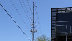
The Polk – Ocotillo circuit is an existing overhead 69kV line that connects the Ocotillo Power Plant in Tempe, Arizona, to the customers’ load point at the Polk substation. The circuit length is approximately 6 miles and is mostly made up of steel poles with some older wooden single and multi-pole structures. The existing conductor is 795 “Arbutus” AAC.
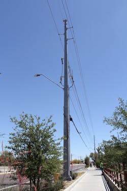
The structures supporting the 69kV circuit also support several other 12kV circuits, secondary circuits, energizing streetlights, transitions, APS communication cables and supports a number of Joint-Use (external communication company) attachments. The Joint-Use cable diameters and unit weights are highly variable throughout the spans of this circuits path. This makes it challenging to determine the overall impact to the existing structures strength capacity. Several methods are being used to quantify these Joint-Use cable details so that the proper magnitude of physical weight and cable diameter are being used in the structural analysis process.
While there are a number of alignment obstacles requiring attention with any project, this one was no exception. For instance, Phoenix Sky Harbor Airport needed special attention due to the FAA’s vertical clearance requirements, elevated overpass roadway clearances, and Light Rail overhead clearance requirements in Downtown Phoenix brought about by direct-current overhead low-voltage bare cables. Along a portion of the alignment, the circuit is built into the underbuilt position on existing 230kV structures resulting in the need to evaluate both vertical clearances below and above. Finally, the circuit crosses the Tempe Town Lake where clearances to waterways will be controlling.
Technology Advancements
To assist in the increased level of analysis & modeling of the existing infrastructure, we utilized Light Detection and Ranging (LiDAR) technology. The LiDAR data capturing activity creates a number of geo-referenced x,y,z points that form themselves into a point-cloud of data points. Each one of these points, or a larger grouping of these points, can be classified and colored to represent the different physical features of the existing terrain. They will ultimately make up the spatial representation of the built infrastructure that surrounds the overhead power lines.
By scanning a power line’s corridor with LiDAR and having those points captured and classified, they can then be imported into the model and each classification can be assigned a required clearance distance that they need to be away from the overhead power lines. We can then use these classified LiDAR points when we are needing to analyze our overhead power lines (conductors) during different physical and electrical loading scenarios. The now-created As-Built model can be used to then study a family of upgraded conductor types to determine which one can fit into the existing environment. These various conductor types also need to be defined with their specific maximum operating temperature based on the higher amount of current to support the increased customer load.

In order to create the as-built structures, which are used inside of the PLS-CADD model, we begin by capturing the field details with a specialized handheld unit called ikeGPS. This device captures a scalable image of the structure as well as the relatively accurate GPS coordinates. We then integrate this data into a PLS-Pole model of the existing structure. The existing model now has the inherent strength properties that are required to identify the existing structure’s strength and its limitations. These As-Built structures are then placed into the model to create the As-Built model of the existing infrastructure.
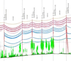
Conductors are now installed and graphically sagged between each of the structures as per the “as-captured conductor temperature,” which was existing at the time of LiDAR. These conductor temperatures are determined by using the IEEE-738 calculation. The structural analysis activity also makes use of the National Electric Safety Code (NESC) ANSI-C2 version of the code that was in control at the time of the structure design and installation. Typically for the Phoenix region, the NESC 250B “Light Loading” values will be governing for historical structural loading analysis.
However, the implementation of site-specific environmental magnitudes now includes “site-specific” loading characteristics (NESC 250C and 250D where applicable) for some of the more recently installed structures. When this “site-specific” loading criteria is implemented, it often creates a scenario where the NESC 250C (site-specific Extreme Wind) loading values overtake the previous impacts of the typical NESC 250B loading values. Therefore, the previously governing load-case criteria (250B) is now being surpassed by the regional site-specific loading values (250C and 250D where applicable).
Now that the As-Built model has been completed, the initial structure check can be completed to review the structural loading (stress analysis) taking place from the field conditions.
Standard vs. Non-Standard
When upgrading an existing circuit from a smaller conductor to a larger conductor, it is often the case where a utility will have a standard conductor to use for the requested circuit/ampacity upgrade. This is also true for APS. However, the standard 69 kV conductor that is used for circuit upgrade projects (795 “Tern” ACSS) has a characteristic that in some cases is unfavorable. Because of the increased current that will flow on the upgraded conductor, the conductor temperature will increase to a value that far exceeds the installed conductor temperature of the previously installed conductor. Because of this elevated temperature and the resulting increased amount of conductor sag means that the electrical clearances between the newly installed 69 kV circuit and the existing 12 kV circuits below could be in violation of the required NESC clearance values. Therefore, when this condition is created, the typical solution is to replace any of the existing problematic
poles with taller poles, which then allows for an increased conductor-to-conductor spacing and thus eliminates the electrical clearance violations.
However, because so many of these poles are built into a very congested and urban environment, removing and replacing them with taller poles with larger foundation diameters will be very costly. In some locations this can be very difficult or nearly impossible due to the amount of existing underground infrastructure that surrounds the old poles diameter.
Instead, if we find a solution that replaces the 69kV circuit with a conductor that supports the higher ampacity requirements from the elevated current flow, doing so will limit the amount of conductor sag and prevent violation of the available 69kV to 12kV phase-to-phase electrical clearances, all while staying within the strength capacity limit of the existing structures.
Previous Installations
APS has gained experience building composite conductor sections in a handful of projects where these were found to be the least-cost option, specifically when compared to the more traditional full structure replacement methods.
One project required an upgraded conductor to fit into a very limited space. This space included two separate 230kV circuits above and ground clearances, streetlights, traffic signals and sensitive vegetation regions below. Composite conductor was successfully used in this space because of its very narrow envelope of minimum versus maximum sag characteristics at the full range of environmental and electrical loading scenarios.
Another example included a double circuit 69kV line built onto existing lattice towers. These towers were not allowed to be modified or rebuilt in any way due to permitting restrictions. It also included a sensitive environmental region surrounding the towers which was off limits to traditional full structure replacement. For this project the selection of the composite conductor was key so that it did not overload the lattice tower’s existing strength capacity. It also needed to support the higher current values while not sagging into the above ground infrastructure or effecting the sensitive environmental regions below.
Composite Conductor Study
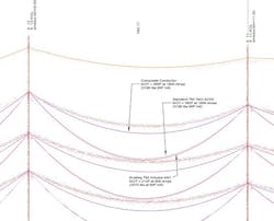
Before moving forward with each of the composite conductor options, the user should also evaluate the standard ACSS conductor in the parametric model to establish a baseline for what the impacts will be if the standard ACSS conductor were to be installed. This would include the formulation of a standard project cost estimate worksheet that includes the determination of the total number of structures that would traditionally need to be removed and replaced as well as each of the construction cost elements that would be required for replacing the structures. This would then act as the total-installed-cost for the standard ACSS conductor type.
Because the existing As-Built model was already available, it was then also used for modeling each of the composite conductor choices. A range of conductor manufacturers were reviewed, and a handful of their composite conductor types were saved into the project’s folder for use in the parametric study.
The study then evaluated a range of conductor characteristics such as 1.) the installed tension value based on the Percentage of Rated Breaking Strength (RBS), used for structure loading comparisons and vibratory stress analysis at the conductor attachment, 2.) the maximum operating temperature (IEEE-738), used for vertical clearance evaluations to adjacent circuits as per composite conductor sag behavior 3.) the conductor outside diameter, used to reduce the transverse load from wind 4.) the conductor weight, used to minimize P-delta loads 5.) the structure loading percentage, used to minimize and eliminate structure overloading scenarios, 6.) the structure replacement costs for overloaded structures, 7.) the hardware installation ease, 8.) the availability of the composite conductor commodities, delivery lead-time concerns, 9.) the cost of the conductor, and 10.) any site-specific qualifiers which may be relevant to the project.
In order to determine which of these characteristics needs to receive a higher value, the user will need to weigh each with a factor to assign a level of importance. Some characteristics may need to be fully achievable rather than just having a beneficial aspect, such as those that contribute to the electrical clearances that are a requirement instead of just creating a benefit outcome such as the hardware installation ease or availability of lead times.
Conclusion of Study
After the range of standard ACSS vs. composite conductor solutions are chosen, compared, and evaluated through the parametric study, a solution can then be realized. This solution will then identify the least-cost-option given the range of existing field conditions, material costs and all of the other factors that are uncovered on a conductor upgrade project.
Ryan Adams has worked in the overhead and underground power line industry for over twenty years. He has a B.S. in Civil Engineering from Arizona State University
and a M.S. in Transmission and Distribution Engineering from Gonzaga University. He is a Registered Professional Engineer in the State of Arizona (53158). Current
affiliations include the ASCE and IEEE.
About the Author
Ryan Adams
Ryan Adams has worked in the overhead and underground power line industry for over 20 years. He has a B.S. in Civil Engineering from Arizona State University and a M.S. in Transmission and Distribution Engineering from Gonzaga University.
He is a Registered Professional Engineer in the State of Arizona (53158).
Current affiliations include the ASCE and IEEE.