You Can’t Push On A Rope: Considerations in Guyed Steel Pole Design
However, guyed steel structures introduce many unique design considerations that impact cost and reliability. To better understand the behavior of guyed steel structures, a study of various design configurations was conducted. From this study, the following were determined to be key considerations influencing the optimization:
- Understanding the complex system of load transfer between the pole itself and its supporting guy wires, anchors and foundation.
- Wind loading and how it influences performance.
- Guy and anchor requirements, the availability of related hardware, and the feasibility of installation.
- Accounting for these unique considerations enable a more optimal design.
Load Transfer on a Guyed Steel Structure
The cost savings from selecting a guyed structure design result from using guy wires to offset the strength needed in the pole shaft and its associated foundation. A guyed structure is optimized when all horizontal forces are resisted by the guy wire or wires and vertical forces are resisted by the rigid structure. This requires the structure to transfer load from the pole to the guy wire, where the load then transfers to the anchor at the groundline.
Given this system of load transfer, guyed steel structures do not have the same capacity in all directions. As a result, the direction load that is applied to the structure is just as important to consider as the magnitude of the load. The load direction significantly impacts how it transfers throughout the structure and which members resist the load.
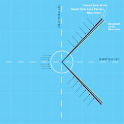
In studying the guyed steel structure system, it became apparent there are two line angles important for design. The first is the line angle derived from the alignment. The second is the line angle calculated from the resultant forces. In most loading scenarios, a deviation exists between the two. There are several causes that result in this deviation. These include wind forces on the wire or structure and load factors that can vary in magnitude in the transverse and longitudinal direction. Though common, this deviation is often not adequately accounted for in design.
However, by orienting guy wires in line with the resultant line angle for any particular load case, the most efficient pole design results for that loading scenario. This would indicate that aligning attachments with the line departure angle may not be optimal. It also indicates that intentionally designing for a guy orientation with a specific offset from the resultant line angle allows for a measurable increase in overall structure capacity.
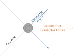
This understanding sheds light on several phenomena of guyed steel dead-end structures specifically. For example, when guy wires are installed in line with the structure’s line angle, guyed deadends with shallower line angles typically require more steel than their larger angle counterparts. This behavior is the opposite of what is observed with self-supporting deadends. Larger angle guyed deadends are governed by intact forces, whose resultants are always on the transverse axis. This allows both sets of guy wires to transfer forces from the shaft to the anchors.
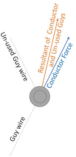
Shallow angle guyed deadends however are governed by one-side-only loading. Under one-side-only loading, the guy wires installed opposite of the broken wires (the “un-used” guys) are unengaged by opposing wires but still apply some force on the pole due to pre-tensioning at installation. The pretension load and orientation of these unused guy wires in relation to the guy wires held in tension causes the un-used guys to contribute to the resultant load. This contribution offsets the resultant from the guy wires in tension, which then requires a more robust shaft design to withstand loading than large angle deadends that are controlled by intact conditions.
As structures are optimized based on the resultant line angle, it is important to consider construction tolerances and how they can be accounted for in design without significantly increasing cost. While fully optimized guyed steel structures provide least-cost solutions, they do not allow for construction tolerance. Good engineering judgement suggests that some tolerance should be factored into design to enable flexibility in the field to adjust to unexpected conditions.
Keeping in mind that as the structure design is optimized to more heavily rely on the guy wire, the structure system will be more sensitive to guy movement. A set orientation angle deviation relative to the resultant load can be used to increase pole capacity measurably to satisfy the specified tolerances allowed during construction. Determining the specified construction tolerances prior to initiating structure design allows them to be incorporated appropriately.
By quantifying how a structure’s individual components are impacted by this deviation and how the components work together to resist various loading scenarios, it is possible to gain greater insight into a structure’s performance. Including this step in the design process enables a calculated effort to optimize guyed steel structures for expected performance.
The Significance of Wind Loading
Wind loading applied in the same direction as wire tension increases the magnitude of the load applied to the structure, and therefore typically requires a more robust structure design. However, recall that the direction of the applied load is just as significant as the magnitude for guyed steel structures and that the direction of the wind load influences the direction of the resultant load the structure system withstands.
While studying various structure configurations, wind was applied in the opposite direction of the wire tension in order to observe how the structure would respond. From this study, it was determined there is a scenario in which the guyed structure is able to resist all of the greatest magnitude loading but fails when a lower magnitude load is applied in a direction the guy wires are not sufficiently supporting. Therefore, we must also consider wind blowing in alternative directions to wire tension.
Given that in some instances it will be the controlling condition for the pole shaft, it was found that negative and alternative wind loading must be considered when designing guyed steel structures.
Selecting a Guy and Anchor System
We know the optimized pole shaft design always results from transferring as much load as possible from the pole to the guy wires and the anchors, but the loading requirements of the guy and anchor design must also be considered. As loading on the guy wires and their associated hardware is increased, at some point design and/or construction limitations can be reached.
Studying the impacts of various structure configurations led to several key observations related to guying and anchoring of guyed steel structures. For instance, the selection of the guy wire size will change the load flow through the system and therefore will also change the optimal guy orientation.
When smaller guy wire sizes are selected for design, the optimal pole shaft design is less sensitive to a changing guy orientation. This is intuitive, given that — for the same loading conditions — the smaller the guy wire size, the greater the capacity of the pole shaft is required.
It was also found that when guy and anchor hardware are appropriately designed, they can allow a large tolerance for guy movement in relation to the pole. This means that whatever deviation from the resultant load the pole may be designed for, the hardware likely can accommodate.
Based on these observations, it is important to recognize the guy wire and associated hardware design is a significant component of the overall structure performance and cannot be regarded as a separate element of design.
Optimized Design
Acknowledging the unique considerations related to guyed steel structure design and understanding their desired application avoids lost efficiencies and yields expected performance. As the industry continues to trend toward implementing these structures as a preferred option to reduce costs, properly accounting for each of these considerations is essential for successful, long-run deployment.
ALEX LEE is a staff transmission line engineer at Burns & McDonnell concentrating on the civil and structural elements of overhead transmission engineering as well as technical writing in the power delivery industry. Her experience includes analysis, design, estimating, and construction support for high voltage transmission lines
69-kV through 345-kV. She received her BSCE from Kansas State University. She is a registered professional engineer in the state of Missouri.
JONDY BRITTON is an associate transmission engineer in the Transmission & Distribution Group with Burns & McDonnell, with a focus on overhead transmission
design and steel design of standard and site-specific equipment. He has experience with structural design/analysis software packages, including PLS-CADD, PLS Pole, PLS Tower and several in-house design programs. He has a wide range of transmission project experience at locations throughout the U.S. and Canada. While helping project teams deliver cost-effective, innovative solutions to clients, he has provided quality reviews, structure design, analysis and existing transmission line modifications.
About the Author
Jondy Britton
Jondy Britton is an associate transmission engineer in the Transmission & Distribution Group with Burns & McDonnell, with a focus on overhead transmission design and steel design of standard and site-specific equipment. He has experience with structural design/analysis software packages, including PLS-CADD, PLS Pole, PLS Tower and several in-house design programs. He has a wide range of transmission project experience at locations throughout the U.S. and Canada. While helping project teams deliver cost-effective, innovative solutions to clients, he has provided quality reviews, structure design, analysis and existing transmission line modifications.
Alex Lee
Alex Lee is a staff transmission line engineer at Burns & McDonnell concentrating on the civil and structural elements of overhead transmission engineering as well as technical writing in the power delivery industry. Her experience includes analysis, design, estimating, and construction support for high voltage transmission lines 69-kV through 345-kV. She received her BSCE from Kansas State University. She is a registered professional engineer in the state of Missouri.
