Avalanche Damage Triggers Constructability Improvements
In March 2019 Xcel Energy in Colorado recorded an outage on the 5007 Cabin Creek to Dillon 230-kV transmission line. The road to the assumed transmission outage location was impassable due to avalanches in the area; therefore Xcel Energy flew a helicopter inspection to identify the issues.
The avalanche danger was extreme in this location and was not safe to access on the ground. Xcel Energy worked with the Colorado Avalanche Information Center (CAIC) to identify additional slide path hazards. A Colorado Department of Transportation contractor was utilized to drop explosive charges from a helicopter to release the remaining slide paths. Over the next few days the avalanche danger level decreased, and Xcel Energy was able to start accessing the site on the ground.
The outage location was near Montezuma, Colorado, which is about 2 miles (3.2 km) west of where the transmission line reaches an elevation of 13,500 ft (4115 m) over Argentine Peak. The transmission line sustained damaged from structures #58 through #64. In the summer this site can be accessed from County Road 260, but in the winter this road is closed to vehicle access due to the deep snow and multiple avalanche slide paths in the area.
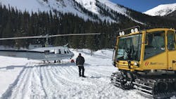
When Xcel Energy received the all clear to access the site, a combination of an excavator and other track equipment was needed to carve out a path along Peru Creek trail roughly 3 miles (4.8 km) long. Until the road was dug out, snowcats were the only means for crews to access the site and assess the damage.
While Xcel Energy construction and engineering began to access the site, the conditions in the area were still favorable for avalanches. Everyone who accessed the site had to be equipped with avalanche safety equipment. The avalanche training and added safety measures were key in making sure all personal had the skills and knowledge to be able to perform their job safely in a potentially dangerous location.
Assessing the Damage
The structures that sustained damage were steel lattice towers installed in 1977. Structures #58 to #62 were tangent H-frame configuration, while structures #63 and #64 were guyed three-leg small angles. The conductor on the line was horizontal two-bundle ACSR 636 Grosbeak with dual 3/8” steel shield wires.
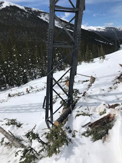
The area with the most significant damage was from structure #61 to #64. Structures #62 and #64 appeared to have taken direct impact from the avalanche slide. Structure #62 was completely collapsed. Structure #64 had its north lattice leg severed from the foundation, which pushed downhill a few feet, but then remained standing holding the wire up. The leg was initially thought to be still connected to the foundation until the snow and debris were removed when it was discovered the leg was only sitting on top of boulders, not connected to the ground.
The Cabin Creek to Dillon 230kV line is important to the reliability of the Xcel Energy system so the project team needed to work quickly to restore the line. Each structure was evaluated to determine if individual members could be swapped out, or if the entire structure should be replaced. The extent of damage on the lattice members was tracked throughout each structure. For those with multiple lattice member failures the entire structure was replaced to save time in fabricating and replacing members and to eliminate unexpected issues that couldn’t be seen in visual inspection of the towers.
With restoration time limited to only four to six weeks, Xcel Energy had planned to replace the damaged H-frame structures with steel poles and fiberglass H-frame
kits. The three-leg angle structures that had a single leg damaged were replaced with a direct embed steel monopole and braced post insulators that were taken from on ongoing project in the Denver area.
Poor access to the site meant cranes and bucket trucks could not be used for construction. All material was flown in by helicopter. A UH-1H “Huey” helicopter was used on this project for all work, which included flying in equipment and material, transporting linemen, and flying out the wrecked-out material. The Huey is a good mid-range helicopter with a lifting capacity of about 2000 lbs (907 kg) to 2500 lbs (1134 kg) at 10,000 ft (3048 m) elevation.
Helicopter lifting capacity is highly dependent on weather conditions, including air density at higher altitudes. With this weight limitation, the steel monopoles were flown to the site in sections rather than being fully assembled. The light duty steel poles that were selected had individual pole sections light enough for the load limit.
Construction Difficulties and Design Improvements
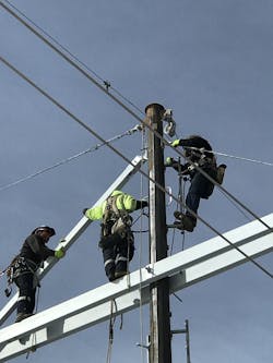
The start of the constructive feedback happened one day as a lineman was working from ladders placed on one side of the pole shaft while trying to drill the hole for the X-brace on the opposite side of the pole. The feedback called down to the engineer was somewhat inaudible but was assumed to be politely asserting the difficulty in drilling the hole in quarter inch steel from the opposite side of the pole shaft. The point was taken and spurred further discussion with the crew onsite about how engineering could modify their design to make working in these conditions easier and safer.
Ladder Clips
Ladder clips are common practice for remote access structures and are most often detailed on structure drawings as being mounted up a climbing face and at working points. Xcel Energy specifies that working ladder clips be placed in four quadrants around the pole at each working point (arm attachments, wire attachments, pole joints, etc.). When a pole shaft has a circumference that is too small at a working point, the steel vendor will reduce the number of working clips around the pole. This potentially results in not having adequate ladder space where a lineman needs to work.
To improve ladder clip design the engineer should clearly define all working points on the drawings that will need ladder clips, including X-brace attachments if they need to be drilled. Also verify adequate ladder clips are available to connect ladders while moving over crossarms.
Wire Rigging
Adequate attachments for wire rigging was also an issue on the angle structures. The angle structures that were replaced with monopoles had braced post insulators with a bundle yoke. These structures had line angles of approximately 8 degrees. The new wire was strung with the traveler hanging on the bottom hole of the yoke plate. To transition the wire from the traveler to the wire clamps the wire needs to be temporarily rigged back to a fixed point on the structure.
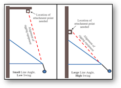
Normally the wire could be picked up with a crane or bucket truck jib, except the site couldn’t accommodate that equipment. With the braced post configuration and only a two-hole shield wire vang at the top of the pole there was nothing to attach the rigging to that would keep the wire at the position needed to pin to the yoke plate. With a tighter line angle the wire could have been rigged off the pole shaft or shield wire vang because it would pull outward more horizontally. With a smaller line angle the wire hangs more vertically, which means the rigging needs to attach more inline vertically above the wire, to possibly a shield wire arm. Since there was not a suitable rigging point, the crew had to use a combination of ropes with the helicopter pulling on the conductor to get the wire from the traveler into the clamps.
All wires that need to be moved from an old position, or from a traveler, to the new pinning position need to have rigging points on the structure when a crane or bucket truck cannot be used. With a suspension insulator hanging from an arm, additional vang holes to attach rigging are needed. With a braced post insulator, a shield wire arm may be needed above to attach the rigging for the conductor.
Line angle must always be considered for rigging attachments in conjunction to the vangs and attachments. Just as a suspension insulator will swing into the line angle, the rigging lines will also swing as they temporarily hold the wire. The rigging attachments need to follow the swing
angle of the wire up and back to a fixed point on the structure.
New Helicopter Guide Tool
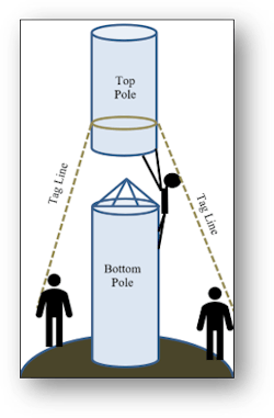
For this project the steel pole sections were flown in separately. As the helicopter lowers the top pole section the crew on the ground holds the tag lines. Sometimes a lineman climbs the bottom pole section and sits atop it to do the final pole guiding and indexing to the correct flats by hand. There are multiple difficulties with this set up.
First, it is very dangerous for the lineman on top of the base section as the 2000-lb (907 kg) steel pole section is swinging under the helicopter. The second issue is indexing the pole section to the correct flats. With tag lines wrapped on the pole shaft there isn’t much leverage or control to spin the pole to the correct flats. With the helicopter hovering and the wind blowing the pole there is very little room for error in slipping the top
section onto the bottom section.
While the construction was still underway, the engineers onsite met with a few linemen in the crew to talk about how certain tools or design modifications could have made the construction process easier and safer. One of the linemen began to draw on the face of one of the steel poles a sketch of a tool that could be fabricated to allow the top pole section to be more efficiently guided and indexed onto the bottom pole section.
The first iterations were scrapped, but this allowed the group to focus in on a removable tool that bolts onto each pole section and acts like a goal post to guide the pole section down. Once back in the office the design was drafted in CAD and the material was selected based on what was available in an Xcel Energy material yard. The raw material that was used was from leftover aluminum bus work and an aluminum lattice tower that had been taken down. The end result was a lightweight, removable, helicopter guide tool.
The “top guide” bolts onto the jacking nuts of the base of the top pole section and is made of two aluminum arms that project horizontally about 2 ft (0.6 m). The arms serve two purposes. The first is for attaching the tag lines out on the arm ends to handle and index the pole easier and safer given the increased leveraged of the longer arms. The second purpose of the top guide arms is to provide increased material area to hit and slide down the “bottom guide” on the bottom pole section.
The “bottom guide” is two vertical arms that are bolted onto the jacking nuts at the top of the bottom pole section. These arms stick up above the bottom pole section and act like goal posts to catch the horizontal arms of the top guide as the pole swings in. Once the sections are slipped together enough to be stable, the aluminum guides can be unbolted and ready to use on another structure.
This avalanche project created a lot of destruction and damage for Xcel Energy in Colorado, but it also created opportunities to advance the engineering and construction techniques around difficult access projects in the mountains. Constructability is the integration of construction expertise and knowledge into the design phase of a project. The open communication between the lineman performing the construction and the engineers preparing the drawings and specifications is essential to increase the constructability of a project. Engineers benefit from understanding how their projects will be built, and construction benefits from understanding the criteria behind a design.
JOSH PETERSON is a principal transmission line engineer at Xcel Energy in Denver, Colorado. He graduated from the University of Wisconsin – Madison with both bachelors and master’s degrees in civil engineering. His experience ranges from 69kV to 345kV design in the low plains to the high mountains of Colorado. Josh is also a member of the ASCE committee ASCE-48 Design of Steel Transmission Pole Structures.
