It Is Not Simple to Secure Steel Davit Arms
Compared with latticed towers, tubular steel poles are a popular structure choice for high-voltage transmission line applications because of their small footprint, ease of installation and fewer structure elements. With modern welding technologies, they also are an excellent option for extra-high-voltage lines. However, aside from these benefits, tubular poles present challenges because of the inherent slenderness of the davit arms. When unloaded, these arms can be prone to vortex-induced vibration (VIV). In this context, “unloaded” means the arm is installed on the pole but no weights, tie-down cables, insulators, conductor or other physical load have been placed on the arm.
Industry guidance recommends all unloaded arms be secured immediately after the arm is installed to mitigate VIV-induced damage, by either hanging weights or tying the arm tips back to the pole shaft with cables. The details (cable types, sizes and weights) of this guidance are nonspecific. Experience has shown not every arm needs to be secured; the actual requirements depend on arm geometry and local wind conditions.
Recognizing a need, American Electric Power (AEP) conducted analytical studies, supplemented by testing, to investigate the effects of wind-induced vibration on various sizes and shapes of davit arms. It is vital to determine the critical wind speeds (CWSs) and their effects on these components. The results of these studies provided surprising insight into when and how to secure an arm. The studies were based on typical davit arm designs used in AEP Transmission line projects.
The Typical Design
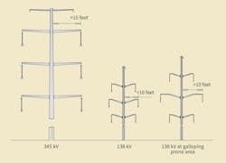
Until recently, most steel pole lines were 138-kV voltage class or below. In recent years, however, more 345-kV lines have been built with steel poles. The length of 345-kV davit arms typically is longer than 15 ft. To meet the voltage-related electrical clearance requirements, 138-kV davit arms generally are less than 10 ft long — unless the transmission line is in a galloping-prone area. The length of the middle-phase davit arm in this case normally will be longer than 10 feet.
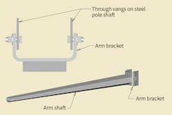
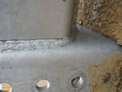
The industry standard for davit arms consists of a tubular steel shaft welded to a bracket. The arm brackets are bolted to through-vangs on the steel poles. Experience has shown wind-induced arm vibration may cause fatigue cracking at the weld toe on the arm shaft within a day when unloaded arms are not secured properly. Conversely, many arms have been installed, without being loaded or secured for decades, that have not developed these fatigue cracks. AEP believes arm geometries, arm-to-pole connection fatigue strength and wind conditions all play a part in this phenomenon.
Calibrating Lab Results
Vortex shedding is a phenomenon that occurs under laminar, steady winds, which drive davit arms to vibrate in the vertical direction. When the frequency of vortex shedding approaches the natural frequency of the arm, harmonic vibration can occur. The resulting dynamic stresses can be large enough to cause fatigue damage. The wind velocity where this condition is met is the CWS.
The frequency resulting from vortex shedding is a function of the wind velocity and arm diameter. It can be calculated using the Strouhal relationship. The natural frequencies of a davit arm can be estimated using calculations in Roark’s Formulas for Stress and Strain (7th edition), which defines the modes of vibration of a cantilever beam. The resulting natural frequency from these calculations should be modified (in this case, reduced) by a calibration factor determined based on lab testing. This calibration is necessary because the calculation assumes the arm-to-pole connection is fixed. In reality, the connection is somewhat flexible.
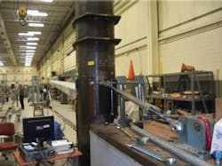
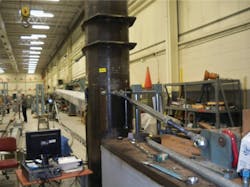
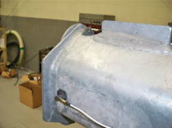
Preformed Line Products (PLP) tested 18 davit arms of different sizes. The supporting pole structure was secured to the floor and back guyed to a reinforced concrete abutment, to prevent it from vibrating. Accelerometers were placed at the end of the arm to determine the natural frequencies for the vertical and horizontal movement of the arm. A reduction factor of 0.95 was determined by averaging the ratios of natural frequencies found from testing to the calculated amount. This reduction factor will reduce the calculated natural frequency and, thus, the CWS, which can cause davit arm VIV.
Appropriate Methods
AEP’s past operating experience and other research indicate, when the wind speed is less than 10 mph or higher than 40 mph, the effects of vortex shedding are not likely to cause damage to unloaded davit arms. For wind speeds less than 10 mph, the wind energy is too low to excite arm motion. Winds over 40 mph typically are too turbulent for the arm to lock into VIV. When the calculated CWS is higher than 10 mph but smaller than 40 mph, the davit arm should be secured properly prior to erecting it, until after wire is installed.
In general, steel pole suppliers and industry standards recommend two methods for securing an unloaded arm:
- Suspending weights or insulators from the arms
- Tying the arm tips together and then to the structure.
Neither recommendation provides detailed specifications about how to implement these in practice (for example, tie-down material and size or tension amount of weights). At AEP, the effectiveness of both methods has been validated by lab testing, as supplemented by dynamic analysis. The results helped to establish the criteria for how and when to secure arms.
Suspended Weights
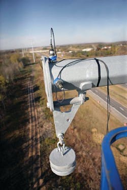
It long has been believed suspending weights from the tip of an unloaded arm reduced or eliminated the effects of possible VIV-induced arm vibration. Decisions about how much weight to suspend was based on past practice. These have included attaching 200 lb (the approximate weight of a string of porcelain bells) or attaching 10% of the arm weight.
Lab testing consisted of suspending three different weights from the tip of the arm: 10%, 20% and 30% of the arm weight (165 lb, 330 lb and 495 lb, respectively). The test measured the natural frequencies and damping ratios, with and without weights installed and in the vertical and horizontal directions. The test results showed suspending weights at the arm tips reduced the natural frequency of the arms in the vertical direction and the corresponding damping ratio. Conversely, suspended weights had little effect in the horizontal direction on the arm’s natural frequency and damping ratio.
The lower natural frequencies resulting from suspending weights on the arms led to lower calculated CWSs necessary to initiate VIV. Structural modeling of the tested davit arms determined the dynamic stress ranges resulting from VIV, by using the lab-measured damping ratios and calculated CWSs for each suspended weight condition. The lowest-predicted stress range of 3.76 ksi (using 495 lb of suspended weights) is larger than the fatigue threshold of 2.6 ksi, per American Institute of Steel Construction (AISC) Category E. This arm may still experience VIV-induced fatigue damage in the field, unless the arm bracket connection uses a full-penetration weld with a backing ring attached to the bracket. This will increase the fatigue threshold to 4.5 ksi, per AISC Category E.
Industry guidance on the amount of weight to suspend does not appear to guarantee the arm will not experience VIV-induced fatigue damage. Based on this, it is recommended the steel pole designer determine the appropriate amount of weight to suspend from an unloaded arm based on the arm shaft dynamic properties, stress concentration factors and fatigue strength of the connection.
Tie-down with Cables
Rope, wire and cable have been used to tie down the steel davit arms in various configurations. These include but are not limited to the following:
- Tying the arms together in pairs.
- Tying all the arms together on one side of the pole.
- Tying all the arms together and then tying them back to the structure.
- Tying each individual arm to the structure.
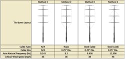
For AEP’s study, the effectiveness of three of these configurations was investigated through structural modeling and dynamic analysis. The option of no tie-downs (Method 1) also was used for comparison purposes.
Method 2 was modeled using rope where all arms were tied together on one side of the pole and then tied back to the pole. Method 3 used 0.25-inch diameter steel cables, tying the arms together on one side and then tying them back to the pole. An initial cable tension of 1000 lb was used. Both methods had little effect on changing the natural frequency of the arm. The arm still could be subjected to VIV, and the cable could be ineffective in stopping the arm from moving.
Method 4 modeled a 0.25-inch steel cable with each individual arm tied back to the pole, using an initial tension of 1000 lb. The results indicated a 27% increase in the natural frequency of the arm and CWS. The resulting CWS was larger than the 40-mph target.
The effectiveness of Method 4 also has been proven through field performance. A larger cable size may be required when the arm length is longer than 20 ft to maintain CWSs above 40 mph. The final steel cable size should be determined by the designer, taking the arm shaft dynamic properties into account.
How and When
As the study results showed, the current industry recommendations on how to secure a davit arm may be ineffective in preventing davit arms from experiencing VIV-induced-fatigue damage. An engineering study is essential to determine the proper guidelines on how and when to secure an arm. Construction personnel should have detailed instructions prior to erecting the structure.
Meihuan Zhu Fulk ([email protected]), P.E., joined AEP in 2006 and is a staff engineer in the transmission line standards group, with responsibilities for structure and foundation design and analysis, conductor motion control and fatigue design. She received a bachelor’s degree in structural engineering from Tongji University and a Ph.D. in engineering from Louisiana Tech University. She is a licensed professional engineer in Ohio; is a member of IEEE, American Society of Civil Engineers, CIGRE, and AISC; and holds 11 patents.
Blake Tucker ([email protected]), P.E., joined AEP in 1997 and is a staff engineer in the transmission line standards group. He received a BSEE degree from Oklahoma State University. He is a licensed professional engineer in Oklahoma, Texas and New Mexico. He also is a member of IEEE and NACE International.
T. David Parrish ([email protected]), P.E., is the transmission line standards manager for AEP. His teams are responsible for all transmission line-related engineering, material, and construction standards and specifications. Parrish is a civil/structural engineer, with considerable structure and foundation design experience in the utility industry. He holds a BSCE degree from the University of Akron and is a registered professional engineer in 13 states.
About the Author
Nancy Z. Fulk
principal and structural engineer
Nancy Z. Fulk ([email protected]) joined American Electric Power Co. Inc. in 2006 and is a principal and structural engineer in the transmission line standards department, where she is responsible for structure and foundation design and analysis, conductor motion control and fatigue design. She received a bachelor’s degree in structural engineering from Tongji University and a Ph.D. in engineering from Louisiana Tech University. She is a professional engineer and a member of IEEE, the International Council on Large Electric Systems, the American Society of Civil Engineers and the American Institute of Steel Construction. She holds 11 patents.
Blake Tucker
Blake Tucker ([email protected]), P.E., joined AEP in 1997 and is a staff engineer in the transmission line standards group. He received a BSEE degree from Oklahoma State University. He is a licensed professional engineer in Oklahoma, Texas and New Mexico. He also is a member of IEEE and NACE International.
T. David Parrish
T. David Parrish ([email protected]), P.E., is the transmission line standards manager for AEP. His teams are responsible for all transmission line-related engineering, material, and construction standards and specifications. Parrish is a civil/structural engineer, with considerable structure and foundation design experience in the utility industry. He holds a BSCE degree from the University of Akron and is a registered professional engineer in 13 states.
