How To Teach An Old Line New Tricks
To mitigate aging infrastructure that had more than exceeded its life expectancy, Brookfield Smoky Mountain Transmission LLC planned to upgrade the Long Span—a 5010-ft, 161-kV transmission line across the Little Tennessee River in southeastern Tennessee. The first line of the Long Span was built in 1917 and the second in 1926. These two lines were the longest transmission line spans in the world at the time. The project upgrade posed interesting engineering challenges and provided a look into the past. The original conductor was custom made and most of the hardware was either custom made or something no one had seen in recent times.
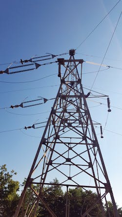
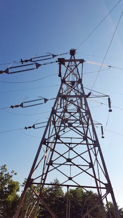
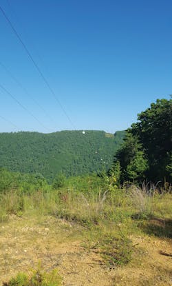
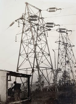
The longest span on these two lines was from towers 117 to 118—on both the A1 and T2 lines. These spans had a horizontal distance of 5010 ft and a vertical elevation difference of 208.5 ft, crossing over the Little Tennessee River where the topography consists of a steep gorge and the river at the bottom. Dead-end towers are located on each side of the span, and each circuit has three-phase conductors in a horizontal configuration with a fourth (nonenergized) conductor and an optic ground wire (OPGW) located above the circuit in the shield wire positions. The fourth wire was installed as a ground wire and as an emergency backup. If needed, the tower grounding could be disconnected, and the ground wire could be energized using bus work on the backside of each of the dead-end towers.
Historical Perspective
Insights into the original technical aspects of the line were gleaned from an article published in the 1920 Journal of American Institute of Electrical Engineers, “The 150,000 Volt Transmission Line of the Knoxville Power Company,” by Alcoa Engineer Theodore Varney. This article described how, at the time of installation, the original 1917 conductor was installed at a temperature of 80°F. The three lower cables were strung in with a sag of 237 ft corresponding to a tension of 19,000 lb per cable. The upper cable was installed with a sag of 216 ft corresponding to a tension of 20,400 lb. The steel core of this custom conductor was designed to carry the full load and terminated with molten zinc into open forged-steel bridge sockets attached directly to the strain insulators.
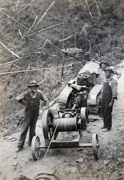
In 1917, lines were built primarily using manpower with donkey teams to assist with moving heavy materials. When the second line was being built in 1926, a custom-made winch connected to the drive shaft of a Cleveland tractor aided in the construction. The crew came up with an inventive way to string the conductor using a special reel brought in by rail located at the bottom of the gorge next to the Little Tennessee River. It was designed so the conductor could be spooled onto the reel in a way that enabled it to be pulled out from both ends simultaneously. The crews then could pull the wire up from the bottom of the gorge to both towers at the same time.
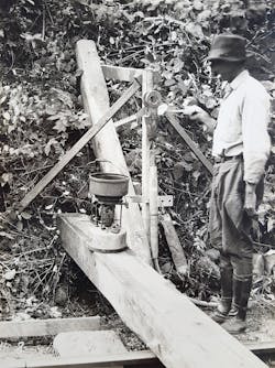
Other unique techniques were implemented, such as building a wooden trough over the rocky and steep terrain to protect the conductor when it was pulled up to the towers and ensure the correct amount of cable was removed off the reel so it was even. The trough had nailheads countersunk so the conductor would not catch and anti-rotation weights were added to prevent the aluminum strands from bird caging. Once the cable was fully removed from the reel, final sag was completed using a manually operated block and tackle system.
Adaptive Approach
The first step in reconductoring this line was to conduct a field visit to determine what to include as part of the project design. Considerations included how to gain access to the site, the conditions of the existing towers and how much of the newer hardware could be reused. The construction of the original line was studied with the goal of marrying the old with the new.
Given the age of the towers, it was important to determine their condition. A soil analysis was performed to ascertain the corrosive nature of the soil. Also, a below- and above-grade tower steel inspection was performed to measure zinc coating thicknesses, identify steel thickness loss and inspect the tower bolts. The towers were determined to be in good condition and corrosion was not a concern.
At the end of the insulator assembly, where the dead-end body attached, two pieces of angle were placed back to back. These angle sections had two holes in them that lined up with corresponding brackets on the tower body on either side of where the insulator assembly attached to the tower.
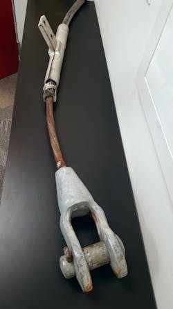
Field operations personnel explained the original 16-ft custom-made turnbuckles for each tower could be bolted in place between the angle assembly and tower, which would give operators the ability to relieve the 30,000-lb tension from the insulators for repairs. This technique also would enable the bells to be replaced quickly and efficiently. Because the turnbuckles were stored at each tower, it was common practice for maintenance crews to apply a heavy layer of grease to the turnbuckles to keep them ready for use.
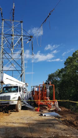
Upon completion of the field visit, a comprehensive scope of the project was developed that included replacing all four wires of the special cable conductor and improving the existing access roads. Because the jumper assemblies for energizing the emergency fourth wire insulator strings and towers were in good condition, they were left in place.
Facing Opportunities
The next challenge was to determine whether reconductoring was feasible. The towers were in good condition, but the tower’s capacity was still unknown. Because the towers were constructed in 1914, the odds of finding the original engineering design with the structure load capacity were slim. Fortunately, information was found by examining Brookfield’s archives.
The main pieces that helped to solve the puzzle were the two data sheet drawings on the long spans. From these drawings, it was possible to determine the physical parameters of the existing conductor and the maximum sagging tension. The two drawings were very similar, with one showing data for the first span erected in 1918 and the other showing data for the second span erected in 1927.
It was not possible to determine the loading capacity of the original towers designed in 1914 because the material strengths and calculations were not available. However, when comparing the applied loads from the existing conditions with the loads applied using the aluminum conductor composite core (ACCC) conductor, the proposed vector loads were less than the existing vector loads for all cases. The long span data sheets showed the original towers to be designed for a maximum tension of 8 kips in one direction and 30 kips (1000 lb-force) in the other direction, resulting in a longitudinal difference of 22 kips.
For the construction phase of this project, an engineering check was required with the custom conductor removed from one side, leaving the original conductor on the back intact. The 8-kips longitudinal load difference (full tension of the back-side conductor) was lower than the difference of the loads with all wires intact. The final determination to use the towers was based on not only the knowledge they were inspected and found to be in good condition but also the loads on the towers would not be exceeded by a smaller and lighter conductor strung at a lower tension.
Some valuable lessons were learned from constructing lines on steep mountainous terrain:
- With spans of this length and size of conductor, double check all equipment ratings. Even a few hundred pounds underrated would be a problem.
- Always prepare a safety plan up front to keep everyone safe during construction.
- Information needed for design can come in many different forms and sifting through available drawings can hold key answers.
Achieving Results
It requires a different perspective and openness to analyze a transmission line with almost a century of proven history and line service, and still be able to ask unconventional questions in light of modern design philosophies.
The keys to this project’s success included a thorough predesign field visit for testing and visual inspection of structures and components, having engineers on-site during construction, creative thinking from start to finish and use of historical information. Also key were the ability to adapt quickly during construction, identify and procure the material needed on-site, and understand upfront there would be some unexpected items that may need to be replaced.
At the end of the day, an old transmission line learned some new tricks by upgrading from a one-of-a-kind custom conductor to a modern ACCC conductor that will allow this line to operate successfully for many years to come.
Jimmy Buker ([email protected]) is an associate, project manager and power delivery lead for HDR Inc. He has more than 13 years of experience as a transmission engineer and, for the last eight years, as a project manager for electrical transmission line projects. He specializes in working with power industry clients, providing project planning, design and construction support services. He received a BSME degree from the Montana State University – Bozeman and is a member of the IEEE PES.
Deborah Knudtzon (Deborah.Knudtzon.hdrinc.com) is a senior project coordinator for HDR Inc., where she has provided project management support to numerous projects in power delivery for the last 10 years. Her primary support has been for transmission and distribution overhead and underground projects. She received a bachelor’s degree in accounting from Montana State University – Billings and is a member of Project Management Institute.
About the Author
Jimmy Buker
Jimmy Buker ([email protected]) is an associate, project manager and power delivery lead for HDR Inc. He has more than 13 years of experience as a transmission engineer and, for the last eight years, as a project manager for electrical transmission line projects. He specializes in working with power industry clients, providing project planning, design and construction support services. He received a BSME degree from the Montana State University – Bozeman and is a member of the IEEE PES.
Deborah Knudtzon
Deborah Knudtzon (Deborah.Knudtzon.hdrinc.com) is a senior project coordinator for HDR Inc., where she has provided project management support to numerous projects in power delivery for the last 10 years. Her primary support has been for transmission and distribution overhead and underground projects. She received a bachelor’s degree in accounting from Montana State University – Billings and is a member of Project Management Institute
