PEPCO and Exelon Work to Keep Transmission Project on Schedule
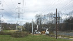
Despite best efforts to minimize the occurrence of unexpected events, sometimes construction on new transmission line projects do not go as expected. Such was the case on a new transmission line being constructed for Potomac Electric Power Co. (PEPCO), an Exelon Co., in Maryland. PEPCO has an ongoing reliability improvement program that involves replacing existing 69-kV wood pole lines with steel poles. For one of the projects in this program, eight tubular steel vibratory caisson foundations were to be installed.
An International Construction Equipment (ICE) Model 44B vibratory hammer with the Model 100BH caisson clamps was used for installation of the steel caissons. Seven of the eight foundations were installed without refusal even though soil conditions generally were stiffer than that typically desired by PEPCO for vibratory caisson installations. Prior to the start of construction, PEPCO obtained soil boring samples at the proposed caisson locations and reviewed the engineering characteristics of each soil sample. During the installation of one of the caisson foundations, the PEPCO refusal criterion was met approximately 4 ft short of the intended driven depth.
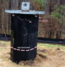
The contractor continued installation attempts for several hours until discovering fatigue cracks were developing on the full penetration welds joining the flange plate to the shaft of the caisson as well as in the base metal of the caisson itself. Obviously, this was a problem that must be solved and solved quickly to avoid significant delays to the project schedule. Many lessons were learned from the practical details that went into resolving this issue and the teamwork that was necessary to bring this unexpected problem to a successful, safe and timely resolution.
Define the Problem
PEPCO engineers immediately began to evaluate the options available. The first step taken was to develop an overall problem statement. PEPCO engineers collected and recorded detailed information on conditions and methods used during installation as well as caisson crack locations and sizes. With that completed, solutions and a plan to execute them could be developed. The utility considered the following alternatives:
1. Evaluate the shorter embedment depth of the installed caisson along with the extra height of the pole to determine whether the caisson could remain as installed with only weld repairs made to the damaged area. 2. Trim the caisson to the intended height above ground and, if feasible, reuse and re-weld the existing top flange. If the top flange were not reusable, then procure a new top flange and weld it to the shortened caisson. Again, the shorter embedment depth of the installed caisson would need to be evaluated.
PEPCO engineers reviewed these two alternatives from a foundation and pole design perspective. PEPCO used LPILE and PLS-CADD to ensure the shorter embedment depth and potential extra height of the pole would meet the criteria of the utility’s transmission standards. When the analysis was complete, it was determined both alternatives were acceptable.
The original design had additional pole capacity incorporated and the transmission standards had been updated recently. These factors allowed a shorter embedment depth and extra height to still meet the design criteria, including deflection and rotation limits. Ultimately, PEPCO preferred the second alternative, trimming the caisson, because the damaged section of the caisson would be removed.
Because of the severity and extent of the fatigue cracks that had formed, PEPOC quickly determined the best course of action for a quality repair would be to remove the top flange of the caisson in addition to the top 4 ft of the caisson. A new top flange plate would be welded to the shortened caisson. Of course, all of this would have to be accomplished on the right-of-way at the location of the foundation.
The next step for the PEPCO engineers was to identify the site-specific and project-specific constraints that might impact execution of the repair. Exo Inc. was engaged to become part of the team to assist the utility’s engineers in evaluating the welding repairs needed and executing them. Exo ensured appropriate weld procedure specifications (WPSs) were in place as well as properly qualified and experienced welders and fitters to execute the field repairs.
Execute the Plan
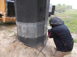
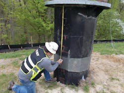
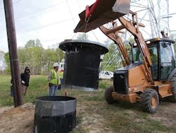
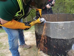
The first step was to measure 4 ft from the existing flange plate and mark a horizontally planer cut line around the circumference of the pole shaft. The below-grade coating was removed at the area of the cut. Using a plasma arc cutting process, the shaft was cut along the marked line as uniformly as possible. Then the damaged portion of the caisson was removed.
The seams for the caisson were not 100% penetration welds, so the seam weld that would now be intersecting the new flange plate weld had to be prepared and re-welded to become a 100% penetration weld, per the requirements of American Society of Civil Engineers (ASCE) 48-11 Design of Steel Transmission Pole Structures standard. Ultrasonic testing verified the weld was free of defects.
The next step was to bevel the top of the caisson to the approved bevel angle on the WPS (40 degrees to 55 degrees). During the beveling process, the zinc was removed in the areas to be welded. Once completed, the horizontal levelness of the prepared top of the caisson was checked with a digital level. If the levelness were incorrect, this would have required additional modifications to the beveled surface to ensure the final installed structure would be plumb.
After beveling and leveling, a new backing bar was installed on the interior of the pole shaft. The backing bar installation followed the requirements of section 5.9 of American Welding Society (AWS) D1.1 Structural Welding Code—Steel. Mill scale and zinc were removed from the new flange in the areas where it would be welded to the top of the caisson. This was an important step to remove contaminants that could adversely affect the final weld quality.
The new flange was lifted and set on top of the backing bar and then measured to ensure it was properly aligned, centered and leveled onto the caisson. After preheating the flange plate to the required temperature on the WPS, the plate was tack welded to the top of the caisson and welding of the flange to the caisson commenced. The preheat temperatures were taken through the thickness of the flange plate plus 3 inches on either side of the area to be welded. The required preheat temperatures were maintained throughout the entire welding process.
Because this welding was being accomplished in the field, it is important to note the welder qualifications had to be completed in the overhead position. In accordance with industry best practices, starts and stops of the weldments were not to be located on the bend lines. Rather, as appropriate, all weld stops and starts occurred in the center of the flats. All fit-up tack welds were ground out so they would not interfere with proper fusion of the flange-to-caisson weld. Once welding started, it continued nonstop so proper preheating was maintained. Temperature readings were taken randomly throughout the welding process.
Once welding was complete, the flange and shaft materials were permitted to cool to an ambient temperature before the weld was inspected. First, a thorough visual inspection was performed, ensuring workmanship requirements of AWS D1.1-2015 Table 6.1 were met. Then ultrasonic testing was performed to ensure the weld had no volumetric defects and met the requirements of AWS D1.1-2015 Table 6.2. All inspections were completed by personnel certified in the requirements of Exo’s written practice, which meets the requirements of American Society for Nondestructive Testing SNT-TC-1A.
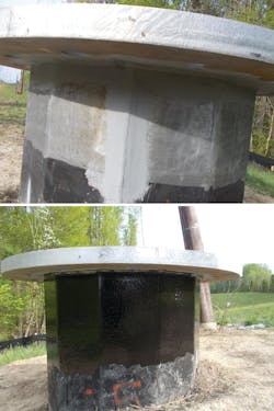
Surface areas that had the galvanizing removed for the repair process were properly prepped and then coated with ZRC zinc-rich paint in conformance with ASTM A780 Standard Practice for Repair of Damaged and Uncoated Areas of Hot-Dip Galvanized Coatings. Proper application and dry time were followed per the coating manufacturer’s instructions.
The below-grade coating also was repaired following the manufacturer’s recommendation. A Monte Profiler was used that creates a 2.5-mil to 3.3-mil surface texture and anchor profile. This profile is important to ensure proper bonding of the coating system to the steel substrate. The profile was tested for conformance using a profile gauge. The below-grade coating was applied to achieve approximately a minimum 20-mil to 30-mil dry film thickness. Thickness measurements were recorded.
The Most Important Lesson
Several important lessons were learned from the practical details that went into resolving this unexpected field construction issue:
- Evaluation of refusal criteria based on total driving time will be considered for future projects, so the caisson is not subjected to the fatigue issues encountered in this project.
- Evaluation of the original design weld details to be used on the various components will be considered to enhance the fatigue resistance of this type of welded assembly.
- When critical welding is involved, it is important to partner with a knowledgeable and experienced remediation contractor who understands the applicable codes and standards related to the work that needs to be performed.
Perhaps the most important of the lessons learned was to understand the value of the dedication to teamwork needed by all parties to bring this unexpected problem to a successful, safe and timely resolution in a quality manner.
Zachary J. Oliphant ([email protected]) is president of Exo Inc. He has spent his 20-year career focused on the manufacturing, engineering, inspection, maintenance and life extension of critical infrastructure assets. He leads a team of technical experts who are specialists at solving client asset challenges.
Justin W. Curtis ([email protected]), ASNT Level III, is a senior technical analyst at Exo Inc. He has spent over 10 years focused on nondestructive testing of client assets and has been involved in quality oversite of projects across the globe. He currently leads Exo’s utility operations group.
Benjamin S. Jessup ([email protected]) is a section engineer at Pepco Holdings Inc. in Washington, D.C. He specializes in transmission standards and materials engineering for overhead and underground transmission applications. He received a BSME degree and a master’s degree in materials science engineering from the University of Virginia and is a member of ASTM International and NACE International.
Christopher W. Schnetzler ([email protected]) is a section engineer at Pepco Holdings Inc. in Washington, D.C. He specializes in overhead transmission engineering projects for Pepco. He received a bachelor’s degree in civil engineering from the University of Maryland and a master’s degree in transmission engineering from Gonzaga University.
About the Author
Zachary Oliphant
Zachary J. Oliphant ([email protected]) is president of Exo Inc. He has spent his 20-year career focused on the manufacturing, engineering, inspection, maintenance and life extension of critical infrastructure assets. He leads a team of technical experts who are specialists at solving client asset challenges.
Justin Curtis
Justin W. Curtis ([email protected]), ASNT Level III, is a senior technical analyst at Exo Inc. He has spent over 10 years focused on nondestructive testing of client assets and has been involved in quality oversite of projects across the globe. He currently leads Exo’s utility operations group.
Benjamin Jessup
Benjamin S. Jessup ([email protected]) is Manager Engineering Transmission Reliability at Pepco Holdings in Washington, D.C. He specializes in corrective maintenance and transmission standards for overhead and underground transmission applications. He received a BSME degree and a master’s degree in materials science engineering from the University of Virginia and is a member of ASTM International and NACE International.
Christopher Schnetzler
Christopher W. Schnetzler ([email protected]) is a section engineer at Pepco Holdings Inc. in Washington, D.C. He specializes in overhead transmission engineering projects for Pepco. He received a bachelor’s degree in civil engineering from the University of Maryland and a master’s degree in transmission engineering from Gonzaga University.
