Rethinking Reconductoring
Transmission system operators are required to provide customers with continuous power. To maintain such a high standard of reliability, operators must plan repair schedules to ensure equipment and assets are well maintained and in full working order.
Every transmission system operator has to make numerous repairs to the network each year and, as a direct result, must manage a series of planned outages, or deenergization, of numerous circuits to facilitate this maintenance work. During an outage period, the network must be reconfigured temporarily, which may also affect the vulnerability of the supply.
Therefore, it is extremely important outage work be kept to an absolute minimum. The continuous linear puller (CLP) is a new concept developed by a collaboration between National Grid Electricity Transmission plc and Tesmec SpA for replacing overhead line (OHL) conductors. Conventional machinery, although much improved, has not fundamentally changed, since its introduction over 50 years ago.
The Current Method
The current method for replacing OHL conductors involves a puller and a tensioner or, more commonly, a two puller-tensioner. The method entails attaching a new conductor to the existing conductor, placing conductor blocks at each intermediate structure, winching in the existing conductor and then coiling it onto an old drum. New conductor is fed in by a factory wound drum, reeved around a large tensioner and then released at a continuous tension to maintain clearance to any underlying obstacle, road crossing or railway infrastructure.
The existing conductor collected onto drums is transported to a recycling facility, where the conductor strands are separated so as not to mix the steel strands with the aluminum. Both these products then are processed into reusable material.
The existing machines designed to pull the old conductor must stop each time a joint in the old conductor arrives at the puller. This joint may be one of the following:
- Existing mid-span splices installed during the main conductor construction phase
- Repairs of conductor in areas where the outer strands have been damaged by externally mounted fittings, such as spacers, fittings, etc.
- Repairs where conductor has been struck by lightning and strands may have been broken
- Line diversions and turn-ins where modifications have been made to the network and conductor has been reused
- At every intermediate pull-through tower where tension insulators are replaced with a short section of conductor, four stockings, a C-connector and swivel.
These joints and connectors are not designed to travel around the surface of the bull wheel on the winch. In fact, the design of the grooves in the outer diameter of the bull wheel is very sensitive to any discrepancy or variation in the circumferential size of a conductor or joint. The passage of joints and connectors around the bull wheels has the potential to damage or break the conductor. Additionally, there is a possibility a joint will get stuck in the bull wheels, which would cause the conductor to sag down, possibly making contact with other lines, buildings or even as far down as the ground.
To avoid the risks, the traditional method implies stopping the winching process on both entry and exit of the machine to connect and remove a temporary joint manually.
On bundled conductor phases, it is worth noting the connectors and joints may not always be aligned; therefore, this entire removal process may be replicated many times during a single conductor pull.
The prior reconductoring technology can be used on anything from 132-kV single conductor up to large-capacity extra-high-voltage networks 220 kV and above, usually in a bundled conductor configuration ranging from two sub-conductors to eight sub-conductors, with drums arranged at the tensioner site and a similar arrangement at the puller site. This requires a considerable area of land and multiple numbers of drum stands to hold the new and old conductor drums; moreover, the project durations will vary tremendously as larger conductors require a disproportionate time to prepare and remove joints.
A New Solution
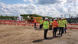
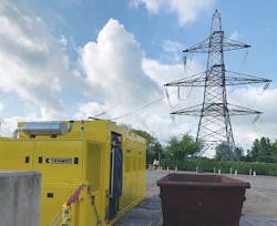
On June 6, 2019, at National Grid Academy in the UK, a new type of machine, the CLP, was demonstrated for the safe collection and disposal of existing conductor (view the demonstration video at https://youtu.be/spQ0NAU_Iu8). Development of the machine started from an existing proprietary technology used for pulling continuous cables.
The new solution consists of a machine that can pull conductor at a continuous speed without having to halt when a joint or connector approaches. The pulling operation proceeds at a constant pace so as not to stress any intermediate support and retains the tension in the conductor during the entire process, even when a joint passes through the winching mechanism. Furthermore, the possibility of collecting conductor in a way that is required by the recycling facility, without the need to recover it in separate coils, has been implemented.
This new solution has the potential to provide several cost and time savings over the conventional method:
- Reduction in circuit outage time (circuit deenergized)
- Fewer contract resources required
- Reduction in the amount of temporary platforms (equipotential zones) that need pulling machinery
- Health and safety benefits as a result of fewer operators working heights and substantially fewer tripping hazards
- Environmental savings across the entire operation.
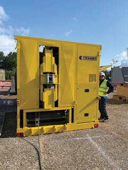
New Machine Concept
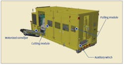
The new puller was designed and manufactured with a four-machines-in-one concept:
- Direct spooling winch located on the front of the machine to assist with conductor loading
- Self-adjusting pulling module with multiple pinch wheels for self-loading of the conductor that enables joints and connectors to pass without stopping
- Cutting module to cut the old conductor in small parts, including mid-span joints and similar devices
- Conveyor system to move the chopped conductor parts into a proper container.
The benefits of the CLP fall into different categories, as some are related to direct costs whereas others are classified as indirect. The largest key benefit is the time reduction in the utility’s outage period, because the contractor can perform the refurbishment process in a timely fashion.
A Case Study
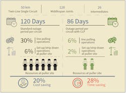
The analysis from a case study by National Grid showed substantial savings in site time, both as direct and indirect costs.
The case study, based on 50 km (31 miles) of a double-bundle single circuit with a total of 128 mid-span joints and 26 intermediate joints, generated a 28% time savings, moving from 120 days to 86 days of outage. In breaking down the time savings, 4% was related to setup and strip-down operation at the puller site and 24% to the pulling operation.
The CLP machine also dramatically reduced the personnel levels required at the puller site, from 6 workers to 2 workers, a savings of 66% in labor expense.
New Job Site
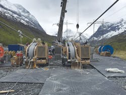
The conventional job site setup is different from the CLP setup because of the types of equipment and personnel required on-site for the pulling operation. On a conventional job site, a range of equipment associated with each pulling machine or winch can be found:
- Powered drum stands (two per sub-conductor)
- Kentledge/ballast weights
- Equipotential zone (EPZ) to support all the machinery
This equipment is used as follows:
- A truck delivers and installs the EPZ as required, depending on the size of the winch and number of drum stands.
- Drum stands and kentledge weights are delivered onto the EPZ and then assembled by the site operatives.
- Drums of coiled scrap conductor are either removed one at a time by truck or tractor and taken back to the depot or are stored on-site and removed by a large truck.
The job site for the CLP may not require any other supplementary equipment apart from the removal of scrap conductor; hence, there is a variation in the number of delivery vehicles that have to travel to the job site to deliver and collect these items of equipment.
In the conventional stringing process, to set up the site, old drums are placed at the puller for scrap conductor and removal requires multiple visits to the site by a truck or tractor, complete with a hydraulic lifting arm. The CLP can reduce the frequency of truck visits because the machine is self-contained and only requires a suitable container to collect the scrap conductor. Site access restrictions require rigorous planning to ensure the scrap conductor is handled efficiently.
The CLP is designed to eradicate the need for conventional take-up drum stands. Instead of drum stands, a large waste disposal container is required to collect all the small pieces of used conductor from the CLP that are dispensed by the conveyor.
Associated with the process of removing the joints prior to entering the machine, the CLP is a continuous process and, thereby, does not require the use of the equipment that temporarily takes the tension of the conductor while the joints are being removed.
Safety and the Environment
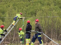
The CLP also eliminates the need to have personnel working heights, thus improving operational safety. It is planned to replace the conventional method of connecting two sections of conductor with a novel connector that can be installed by the operatives as simply as the conventional equipment. This enables joints and connectors to pass through the CLP without stopping; hence, they are classified as consumables.
The CLP potentially eliminates the need for the EPZ provision. The purpose of the EPZ is to connect all parts that may be accessed by operators in the event that, with an unplanned reenergization, all items rise to the same voltage level. The CLP processes conductor without the need for the collection of conductors onto drums, resulting in operators not having to come into contact with conductors. Operators have the option of either standing on a designated footplate or operating the machine by radio remote control and being nearby the machine but not in direct contact.
The new process also introduces a new environmental feature. The traditional process of recovering aged conductor often can generate many particles of aluminum oxide that, in certain conditions, can cause potential issues for site personnel, the area around the machine and the actual pulling machinery, as these particles are very abrasive. The CLP device has been designed to collect these dust particles during the recovery of the conductor and remove them at the source, so particles do not become airborne.
The Next Evolution
The newly developed CLP is a proven concept for the replacement of OHL conductors in the energy sector. The CLP machine can be complemented by new items to potentially introduce further advancements from the conventional tension stringing system, moving from the CLP to the continuous pulling system (CPS). New stringing concepts currently are in the feasibility evolution and prototype phase to provide even further benefits:
- Minimize the pulling tension value to prevent conductor damages.
- Maximize the collection of scrap conductor.
- Minimize dead time at the tensioner station when replacing old reel with new reel of conductor.
- Minimize the time of execution of mid-span joints or temporary connections.
- Minimize the clipping operation time after the stringing operation.
For more information:
National Grid Transmission plc | www.nationalgrid.com
Tesmec SpA | www.tesmec.com
About the Author
Doug Galloway
Doug Galloway is the circuits technical leader for National Grid Electricity Transmission plc in the United Kingdom. He leads the utility’s technical strategy and direction for overhead line and cable technologies. With more than 30 years of experience in the industry, mostly on the contractor side, Galloway moved to the client side more than six years ago and has been in this role for two years. He is a chartered engineer and member of the Institute of Engineering and Technology (IET).
Alberto Oscar
Alberto Oscar is chief technology officer of the stringing division at Tesmec SpA in Italy, where he leads a large team of research and development engineers involved in the design and manufacturing of T&D overhead and underground power line stringing machine and equipment. He has a degree in mechanical engineering from Politecnico Milan, Italy, in 1988. He is an active member of the Commission Electrotechnique Internationale/International Technical Commission (CEI/IEC) TC 11 Overhead Lines, TC 78 Live Working (WG 11 Technical Support) and TC 20 Electric Cables; CIGRE SC B2 Overhead Lines (WG B2.66 Safe Handling and Installation Guide for High-Temperature Low-Sag Conductors); and IEEE.