Corrosion Risk Mitigation
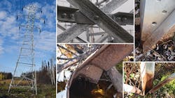
Corrosion is a primary cause for in-service degradation of steel structures in T&D lines, sometimes assisted by mechanical and microbiological actions, depending on the nature of the service environment. Nowadays, most power utilities manage a large population of aging structures, and corrosion has become a serious financial and technical challenge.
A recent CEATI International Inc. report, Guide for Cathodic Protection of Transmission Line Structures (Transmission Line Asset Management 3256), aims to increase awareness within the utility industry of corrosion-related issues and takes initiative to outline corrosion assessment and mitigation techniques for electric power transmission infrastructure. It provides a fundamental understanding of corrosion mechanisms specific to T&D structures and outlines the various conditions under which different corrosion scenarios can occur on the below-grade and above-grade components of these structures.
The report also discusses different types of foundations and relevant cathodic protection (CP) systems for each type of foundation.
Corrosion Risk Assessment
When a structure corrodes to the point where it starts experiencing structural corrosion (severe material loss), risk-mitigation practices cannot be applied effectively, and a structure repair or replacement becomes the only viable option. Accordingly, it is essential to detect and control corrosion in its early stages, before it leads to structural failure and, in turn, results in power systems outages, environmental damages, injuries or fatalities.
Since inspection of a large number of structures is not practical, a prioritization process is recommended to assign a corrosion risk factor to each structure or sections of a line. For this, archival data must be compiled and specific importance weights should be assigned to the following factors:
- Line importance (may include a combination of different factors such as voltage and proximity to the public)
- Structure age
- Structure type (foundation design)
- Structure material (galvanized or non-galvanized steel)
- Grounding system design
- Geographical location (taking into consideration the corrosivity of the service environment)
- Proximity to pipelines and other sources of stray current
- Presence of corrosion control system (coating and CP system)
- Inspection and maintenance history.
Based on predefined criteria, field inspections must be scheduled for structures with the highest priority or risk. The inspections may be performed in two levels. Level 1 inspections focus on the corrosivity of the soil service environment and usually require the following tests:
- Structure-to-soil potential measurement
- Soil resistivity test
- Soil pH tests
- Material and coating thickness measurements at grade level
- Visual inspection at grade level for signs of corrosion.
Based on the outcome of the level 1 inspection, a level 2 inspection may be conducted for selected structures at more corrosive environments. This involves the following steps:
- Excavations of 0.5-ft to 3-ft (0.15-m to 0.9-m) depths and cleaning of corroded members
- Visual inspection and photographic documentation (close-up photos from corroded areas)
- Material and coating thickness measurement at below grade
- Pit depth measurement (ASTM G46).
Cathodic Protection
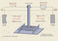
CP is an electrochemical corrosion control technique. It is proved to be an efficient and cost-effective method to mitigate ongoing corrosion in steel structures. By application of a CP system, corrosion reactions at a structure are manipulated by pumping electrons to the structure. This can be achieved by installing anodes at the footing of the structure. The function of anodes is to polarize the corroding surfaces of the structure with a protection current. Based on anode materials, CP systems are divided into two categories: galvanic CP systems and impressed current CP systems.
In galvanic CP systems, anodes are commonly referred to as sacrificial anodes, as the anode material depletes gradually during protection of the structure. Anodic reactions are shifted to the anode buried near the structure while electrically connected to the structure to supply electrons. In this setting, the structure becomes the cathode in the corrosion cell, thus no material loss occurs on the structure surface.
Unlike pipelines that are long continuous structures and represent large surface areas, foundations of transmission towers are discrete structures with much smaller surface areas. This means the application of galvanic CP systems for transmission and distribution structures is favored over impressed current CP systems; however, the main drawback of sacrificial anode systems is their inefficiency in high-resistivity soils.
Anode Bed Design
Because of variations in soil characteristics, the design of CP systems varies from one structure to another, even for structures with identical geometries. Nonetheless, it is not economically feasible to collect field data for all corroding structures along a power line and to design individual CP systems for each structure. Instead, a desk study must be performed to select a few structures that represent the condition of all similar structures in the line and perform field survey on these representative structures.
The objective of anode bed design is to establish an optimum protection current for buried components of the structure. This requires soil service environment characterization, corrosion status evaluation at the structure, anode material selection, anode weight calculation (based on the structure’s size and required life span of the CP system), anode number selection and anode arrangement considerations.
Details of anode bed design for CP of transmission and distribution structures are discussed in the Transmission Line Asset Management 3256 report. A design life of 10 to 15 years is common for CP systems with galvanic anodes in soil environment. Anode consumption (the material depletion rate) and anode passivation (the formation of a resistive barrier oxide film) are two operational factors that influence the life span of galvanic anodes. Furthermore, the life span of anodes depends on design parameters such as material type and anode mass.
Magnesium and zinc alloys are the preferred anode materials for soil applications. For magnesium anodes, the two most common alloys are the high-potential alloy M1, per ASTM B843, and the AZ-63 alloy, also called the H1 alloy. There are three different types of zinc alloys: high-current zinc anodes, zinc alloys based on ASTM B418 and anodes based on MIL-A-18001K. It is important to mention that for CP of transmission towers, the use of zinc anodes is recommended only for soil resistivity values less than 10,000 ohm-cm.
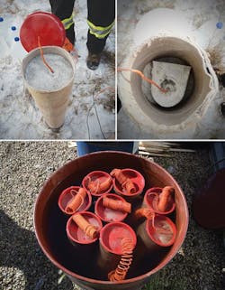
Most magnesium and zinc anodes used in soil environments require the use of prepared backfill around the anodes. Anodes with backfill materials — usually a combination of gypsum, bentonite and sodium sulfate — are called packaged anodes. Such materials, besides restricting the formation of surface films and preventing electroosmotic dehydration, act to provide uniform current delivery and uniform material consumption. Standard backfill material must provide a uniform resistance of 50 ohm-cm when measured by the soil box test method, ASTM G187.
The conventional CP design procedure was originally developed for piping systems. In the TLAM 3256 report, it has been modified and extended to T&D structures.
A critical part of CP design is to determine the amount of required current to protect the structure cathodically. The required current can be estimated from tables and charts based on field experience or from current requirement tests using a temporary anode bed. The required current for CP is a function of soil characteristics, the structure’s geometry and the surface condition at the soil-structure interface. Some of the important parameters include the bare surface area, coating resistance, ionic conductivity of soil, soil pH level, soil temperatures and soil aeration level.
Once the minimum mass for anode material is calculated, the layout of the buried anode around the structure (the anode bed) must be designed. The key questions in anode bed design are the number of anodes as well as the distances between an anode to other anodes and the structure.
One may decide to use a single anode with the minimum calculated mass or multiple anodes with a total mass equivalent to the calculated mass. Selecting a high number of anodes usually improves the performance of the CP system, as it usually leads to a more uniform distribution of protection current. However, it increases the interference between anodes and, more importantly, results in a higher cost of system installation and maintenance.
Once the number of anodes is selected, the next question is how the anodes should be distributed around the structure. If the distance between the anode and the structure is too far, the soil resistivity leads to a large potential drop, and the required polarization for CP cannot be achieved on buried surfaces. On the other hand, if the distance between the anode and the structure is too short, a uniform current cannot be established, meaning some surfaces become overprotected while others become underprotected.
Indeed, for utilities, the ideal case would be minimized anode material cost and installation expenses while a sufficient protection level is provided. Providing such optimized designs requires computer simulations, however, computer-aided design platforms for CP systems are mostly developed for pipelines and offshore structures.
Computer-based models for CP systems can accommodate design features missing in conventional design methods. The conventional methods, still widely used in practice, are mostly based on empirical formulas and engineer or technician experience. Although useful, such design methods are not optimized and cost-effective because they fail to incorporate geometrical factors and transient design parameters, thus requiring the use of relatively large safety factors. For one design scenario, several anode arrangements may be proposed where all of them could be equally effective, but, in most cases, only one optimum arrangement exists for anode beds.
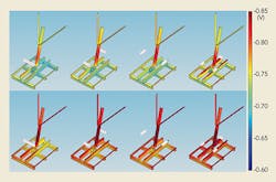
For example, grillage foundations represent a high level of geometrical irregularities (edges, holes, bends and joints), and the design of the CP system for this type of foundations has proven to be a challenge. Four different anode beds with horizontal anodes (white cylinders) are considered, as presented in each column. Results in the top row correspond to neutral soil with a soil resistivity of 5000 ohm-cm.
To show the effects of soil resistivity on CP performance, simulation results at a slightly acidic soil with resistivity of 2000 ohm-cm are presented in the bottom row. To provide a fair comparison between two cases, the size of anodes is not changed, although it is apparent that required CP current increases as the corrosivity of soil increases, which, in turn, increases the required mass for anodes for a certain CP system life.
Performance Assessment
Distribution of potential on buried surfaces of the foundation is investigated to assess the performance of each anode bed design. According to the NACE SP0169 standard, a minimum surface potential of -0.850 V vs. CSE is required for CP of steel. The dark-red areas in the simulation results are the protected portions of the foundation while the orange, yellow, green and blue areas, in that order, represent partially protected surfaces. The results clearly show anode beds provide better protection in soils with lower resistivity. Also, it can be seen highly distributed anode beds lead to more uniform coverage.
The computer simulation also shows areas with geometric features such as corners and edges, located near the anodes, receive the maximum protection current, whereas flat surfaces, particularly shielded surfaces, are least polarized and protected. As a result of geometrical complexities, multiple anodes for CP of grillage-type foundations are recommended.
Furthermore, at soils with high-resistivity values, it is necessary to consider a higher number of anodes and bury them close to the structure — less than 2 ft (0.6 m) away — to achieve a good level of protection. For large grillage-type foundations, horizontally buried anodes are preferred to protect the horizontal members of the grillage, while vertically buried anodes are recommended for protection of vertical (leg) components. Nonetheless, it is always recommended to provide full CP to critical members of the foundation under maximum stress — usually the legs — thus, a combination of vertical and horizontal anodes may be required.
Acknowledgement
This article is the result of Transmission Line Asset Management 3256, Guide for Cathodic Protection of Transmission Line Structures, undertaken for and funded by the members of CEATI’s transmission line asset management (TLAM) and transmission overhead line design and extreme event mitigation (TODEM) interest groups.
Peyman Taheri is the director of engineering at Matergenics Engineering. Taheri is a professional engineer and a member of NACE and ASME. He is a NACE-certified CP technician, experienced in the design and installation of cathodic protection systems. His industrial experience includes corrosion inspection, corrosion risk assessment and corrosion risk mitigation in power and telecom utility structures.
Badia Bachour is a civil engineer on the lifecycle maintenance engineering team at AltaLink in Calgary, Canada. Bachour is a professional engineer in the Association of Professional Engineers and Geoscientists of Alberta and a member of NACE. She completed the academic requirements to obtain the NACE corrosion technician certification. Bachour is leading the design and implementation of the corrosion maintenance and mitigation program at AltaLink.
Darren Wiebe is a transmission line engineer at SaskPower, the principal electric utility in Saskatchewan, Canada. He is a professional engineer, project manager and a NACE-certified CP technician. Through providing expert advice and direction on the management and administration of transmission line projects, Wiebe has successfully executed numerous multimillion-dollar capital and maintenance construction projects and contracts on 72-kV or greater transmission lines.
Alex Mogilevsky is a graduate of Moscow State Technical University in electrical engineering and a T&D manager at CEATI International Inc. He oversees the development of the company’s overhead T&D asset management program as well as several special programs for electric utilities, including protection and control, grounding and lightning, power system planning and operations, and smart grid.
Mehrooz Zamanzadeh is a NACE-certified specialist in corrosion, coatings, materials selection and design, and cathodic protection. Among his credits are a variety of awards, including the NACE Fellow Award, ASM Fellow Award and Colonel Cox Award. Zamanzadeh has performed corrosion risk assessment and failure analyses investigations involving corrosion, coatings and materials damage in the construction, oil and gas industries, and on aging utility and aircraft components.


