Less Sag, More Power: Israel Refurbishes Transmission Lines
Utilities continue to face an abundance of technical hurdles, not the least of which is the transmission and distribution infrastructure. As the demand for electricity continues to grow, so do the increasing challenges of upgrading the existing infrastructure and building new transmission circuits. As a result, utilities are looking for new and innovative ways to increase circuit capacities and maintain system reliability.
The Israel Electric Corp. (IEC), which is currently experiencing an increase in demand of 3.5% per annum, has a transmission system comprised primarily of 400-kV and 161-kV ac overhead lines. The older lines were built with aluminum conductor, steel-reinforced (ACSR) conductors, but more recent lines have been constructed with low-strength, high-conductivity all-aluminum alloy conductors (AAAC). The difficulty of securing rights-of-way for new lines and budget restrictions some 15 years ago forced IEC to consider uprating existing lines rather than building new lines or reconstructing older lines.
During this period, most of the transmission lines with conductor operating temperatures in the range of 60°C to 80°C were uprated to 100°C, providing an ampacity increase of 70% or 40%, respectively. However, the demand for power has now reached the limit of the prior thermal uprating. Therefore, IEC has had to launch a second phase of conductor uprating whereby existing conductors will be replaced by high-temperature, low-sag (HTLS) conductors. The new conductors will effectively increase the circuit ampacity by an additional 40% to 50%, as the HTLS conductors will allow a continuous conductor temperature of at least 200°C.
Existing Line Limitations
A precondition of this reconductoring project was to avoid design changes to the existing supporting structures, other than repairs needed to restore them to their original performance. This stipulation meant the HTLS conductors had to meet the same structure loading and high-temperature sag limitations as the existing line structures.
The spare ground clearance on the original lines was used when the first phase of circuit uprating to 100°C operation was undertaken. In addition, methods such as structure and suspension hardware modifications were used. The uprating objective for the second phase was to ensure the sag associated with the new HTLS conductors, operating at 200°C, should not exceed that of the existing conductors, operating at 100°C.
The wind standard in Israel was revised recently to increase the design wind loading on existing line supports. As the majority of IEC’s transmission lines were built before the higher loading requirements, the utility is not required to strengthen these lines. However, the lines are now considered overloaded so no additional structure loading is permitted. For the recently constructed transmission lines, the structures have sufficient surplus strength to absorb the additional loading.
Conductor Selection
The composition of the HTLS conductors, designed for 200°C operation, includes a messenger — often referred to as a core — that consists of steel available in different strength grades, Invar, composite materials, and a conductive layer of thermally resistant aluminum-zirconium alloy or annealed Type A1 aluminum (1350 H-0 aluminum). Following preliminary thermomechanical calculations, IEC selected an aluminum conductor, steel-supported (ACSS) conductor that not only met the required criteria but also had the lowest cost of any of the alternative conductor designs considered. Further, ACSS has the longest service history and track record for reliable service.
The Galfan (zinc 5% aluminum-mischmetal alloy-coated) steel coating is suitable for high-temperature operation in most cases, while aluminum-clad steel will be specified for extremely corrosive environments. Trapezoidal-wire (TW) compact conductor designs were evaluated, but the diameter-equivalent TW conductors are heavier and could overload the structures. Area-equivalent TW conductors have a lower heat-dissipation surface and, consequently, a lower ampacity. Therefore, IEC ultimately selected an HTLS conductor with conventional round-strand construction.
Initially, it appears the steel core conductor lacks the advantage of the extremely low thermal elongation offered by Invar or composite cores. However, the minimal steel content reduces the conductor weight, enabling a higher tension-to-weight ratio and, consequently, a lower initial sag within the maximum structure tension limitations. Aeolian vibration is not a concern because of the good self-damping characteristics of ACSS. Alternatively, the high elasticity of the thin steel core compensates, to a large extent, the thermal elongation.
Conductor Prestressing
The final step required to resolve the sag problem was the prestressing of the ACSS conductor. Tensioning the conductor to values above its maximum expected tension, before sagging, transfers the load from the aluminum to the steel core, minimizing the conductor thermal extension and maximizing the elasticity. In addition, this prevents creep and improves self-damping. There are three main advantages of conductor prestressing:
- There is no need for vibration dampers.
- Small birdcages that appear mainly near compression accessories are corrected during the prestressing and require no special attention.
- The final sag is visible and measurable, not calculated.
A sag comparison was made between the original 300/50-mm² (0.465/0.0775 in²) ACSR after the creep period and the new 636-kcmil (322.2/31.5-mm²) [0.499/0.0488 in²] 22/7 Goldfinch/ACSS/HS AW with the same outside diameter as the ACSR and reduced (31.5 vs. 50 mm2) steel content after prestressing. The calculations for ACSS were made using SAG10 software from Southwire. SAG10 can model prestress and the tension division between the steel and aluminum layers. The results of the comparison confirm that ACSS sag at 200°C does not exceed ACSR sag at 100°C. Therefore, all sag requirements of the design are met.
As a result of its lower weight, the ACSS conductor’s thermal sag is less than that of an ACSR conductor, which sags more for the same tension because of its higher steel content. However, with its extremely high elasticity, the ACSS conductor elongates much more under wind load and does not develop excessive tension. Following IEC’s pilot installation, the short spans were tensioned to values less than that used in the comparison as the surplus ground clearance was not required.
Therefore, IEC determined the principal conductor choice for its ACSR conductor replacement was the ACSS conductor of regular (not compact) structure, with the same diameter and minimal steel content. IEC selected standard Goldfinch/ACSS and Bobolink/ACSS to replace the comparable ACSR sections, all having a lower steel content than the original ACSR.
IEC’s Pilot Project
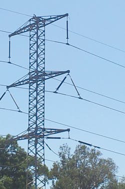
A double-circuit 161-kV transmission line was chosen for the pilot project. It is 12 km (7.5 miles) long and was built 40 years ago using conductors with a maximum operating temperature of 60°C, which were subsequently uprated 15 years ago with conductors with a maximum operating temperature of 100°C. Each phase was a single 300/50-mm² ACSR conductor. The line route crosses an industrial area with high air pollution and is erected in close proximity to the Mediterranean Sea.
IEC selected a 636-kcmil 22/7 Goldfinch/ACSS/HS AW with aluminum-clad high-strength steel for maximum corrosion protection. This meant less steel content in the conductor and greater ground clearance, so IEC was able to eliminate uprating many suspension insulator strings. A maximum conductor prestress of 3,000 kgf was selected, which is more than the maximum tension with wind (2,700 kgf), resulting in zero tension of the aluminum at temperatures above 30°C to 40°C.
The conductor was supplied by Southwire and the high-temperature accessories were made by ACA. Both companies trained and instructed IEC crews on the conductor installation at the utility’s linemen training site.
The installation procedures for stringing HTLS ACSS conductors are not that different from stringing ACSR conductors, but some specific observations were noted:
- IEC measured the tension variation during the prestress process, and it was found the tension decrease leveled off after 15 minutes, so the prestress time was redefined to 20 minutes.
- At all stages following prestressing, the conductor tension should not be lower than the final (sagging) tension; otherwise, the mechanical effect of prestressing may be partially lost.
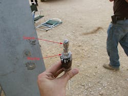
- It was found the pulling sock failed to secure the steel core of the Goldfinch conductor from sliding inside the aluminum. Therefore, a stopper was used under the pulling sock, consisting of a washer and sleeve, compressed on to the core.
- The pulling grip was found to crush the aluminum at conductor tensions of about 1,700 kgf, so IEC decided to use a double grip between 1,500 kgf to 3,000 kgf. The double-grip configuration consists of two pulling grips connected together through a pulley, thus the tension force is equally distributed.
The pilot project transmission line is heavily loaded, and IEC was forced to work on one circuit with the adjacent circuit energized, and sometimes even between two energized circuits. At the large line angles, insufficient electrical clearance proved to be a problem. The angle is not critical at the pulling end but may be problematic at the early structures and at the angle structures.
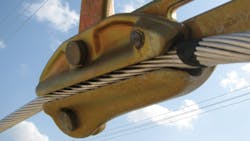
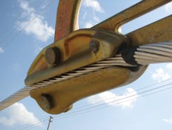
The ACSS requires bigger stringing blocks at the angles than regular ACSR. However, the standard blocks of this size are heavy, and IEC was not certain ACSS could bear this weight without damaging the aluminum. So, a light stringing block was used at these angles. The block was originally developed for optical ground wire, which is also more sensitive than regular conductors. It is three times lighter than a standard block of the same diameter and, furthermore, its center of gravity is much higher. More of these blocks, used also at suspension structures, will ease the linemen workload.
The Benefits
The reconductoring of transmission lines with an HTLS conductor increases the line ampacity by about 50% compared to the capacity available from a circuit with an ACSR conductor that has a maximum operating temperature of 100°C.
ACSS conductors of standard design are suitable for the climatic conditions in Israel. The characteristics of no ice accumulation on conductors, reduced steel content, low weight and high elasticity solved the sag problem and increased the ground clearance in some instances. These benefits were achieved all with no increased loading on the suspension and tension steel towers.
Prestressing the ACSS before sagging is effective for reducing the final sag. This prestressing should exceed the maximum expected conductor tension, and the aluminum plastic deformation should ensure that, within most of the operating temperature range, only the steel core is carrying the line tension.
Apart from the need to use some special tools and accessories, the reconductoring process using ACSS HTLS conductors is not very different from stringing lines with ACSR conductors.
Arie Leib Tukachinsky ([email protected]) has served as a consulting engineer in the overhead lines department of the national network unit at the Israel Electric Corp. for the last two decades. He has a MSME degree as well as a master’s degree in mathematics.
Companies mentioned:
ACA| www.aflglobal.com
Israel Electric Corp.
Southwire| www.southwire.com
