Field Note – Lightning Performance of Spacer Cable – Nov. 30, 2017
Power system professionals often ask about the lightning performance of spacer cable, and how it compares to that of bare wire. The purpose of this field note is to address that question.
Design Objective
With spacer cable, the objective is to have a higher impulse strength than what could be presented by a lightning impulse.
Background
The average North American strike is 40kA, with some strikes coming in as high as 100kA, and, in some cases, even as high as 200kA. In a spacer cable system, the lightning strike will impact the messenger, and travel to ground. By Ohm's Law, the current in the strike, multiplied by the impedance (Z of the messenger plus Z of the ground wire plus Z presented by earth at the point of grounding) equals voltage. It is that voltage rise at the point of strike, or at the pole (specifically at the messenger) that is of concern. If that (high frequency) voltage rise is higher than the system BIL at that point, there will be a flashover, and potentially, some damage. Therefore, we want to have a higher BIL, or impulse strength (measure in KV) than the impulse voltage impressed on the system by the lightning strike.
Most strikes in North America are negative impulse strikes (ie, from the ground to the sky), while in the southern hemisphere they are positive impulse strikes. This leads one to look at negative impulse withstand or positive impulse withstand, depending on where (which hemisphere) they are. A trend in the industry is to simply look at "critical Impulse Withstand" and simply not worry about positive or negative.
Configurations and Scenarios
With spacer cable, we have two mounting scenarios to consider. The cable either mounted on a spacer, or it is mounted on an insulator. As such, we have two series impulse strength combinations to concern ourselves with. The two cases are described below.
1. Cable mounted on a spacer:
* The breakdown path here would be from the cable, to the messenger (or visa-versa), giving us two impedances, or impulse strengths, in series.
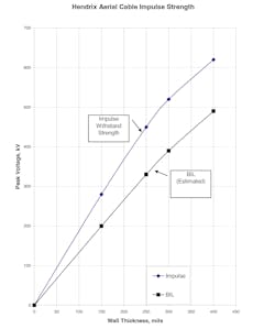
The impulse breakdown strength (BIL, or breakdown when hit with an impulse waveform of shape 1.2 x 50 microsecond waveform) of cable alone is shown in the accompanying chart.
Impulse tests yielded varying breakdown values, and it was decided to assign a BIL lower than any of the test results. If the test was redone today, we would likely be a bit more rigorous from a statistical test design protocol (ie, rate it a -3 standard deviation from the lowest test point value). The above numbers would still hold up, however.
Suffice it to say, the cable itself has a BIL of approximately 200kV for a 15kV cable, and a higher BIL for higher voltage rated cables. Now we need to consider the breakdown strength, or BIL of the spacer.
The Breakdown strength of a spacer was tested years ago. It is essentially a worthless test, since one puts bare wire in each saddle position and hits the messenger position with an impulse. The flashover occurs in air, so the test is only verifying the breakdown strength of air, and is totally unrelated to the spacer itself. BIL for air is around 6.56 kV/cm (16 kV/in), depending on altitude, humidity, etc.
The BIL tests for the RTL46 and a 25 kV cable sample were done a few years ago in a client’s lab and gave higher numbers for BIL than shown in the chart above.
So, the combined BIL of the cable mounted in a spacer would be that presented by the cable, and the spacer, in series. Unfortunately, one can not add impulse strengths linearly. However, it would be reasonable to say that at 15kV, our system would present an approximately [200 + 8.5(16)], or about 336 kV BIL. The numbers would go up for thicker wall cables and/or larger spacers. Those numbers are shown in the below table.
| kV Class | Cable BIL (kV) | Spacer | Air Gap Ph.-Gnd (in.) | Spacer BIL (kV) | System BIL (kV)15 |
| 15 | 200 | RTL15 | 8.5 | 136 | 336 |
| 200 | RTL46 | 11.75 | 188 | 388 | |
| 200 | RTLGO95 | 18 | 288 | 488 | |
| 25 | 325 | RTL46 | 11.75 | 188 | 513 |
| 325 | RTLGO95 | 18 | 288 | 613 | |
| 35 | 395 | RTL46 | 11.75 | 188 | 583 |
| 395 | RTLGO95 | 18 | 288 | 683 | |
| 46 | 495 | RTL46 | 11.75 | 188 | 683 |
| 495 | RTLGO95 | 18 | 288 | 783 |
2. Cable mounted on an insulator:
Even in a spacer cable configuration, on angle poles, the cable is mounted on a pin type insulator. As such, the breakdown path would be from the conductor to the insulator pin, either through the insulator, or across the sheds.
So the BIL, or Negative Impulse Flashover that would be presented by the spacer cable system at the insulator position would be a function of kV class cable, and insulator used. The system BILs achieved by various typical combinations are shown in the chart below. It should be noted that it is possible to increase the BIL by using other insulator options (ie, such as the ANSI 55-4 at 25 kV, or using the Vice-Top insulator at any kV class, which will add 20-40 kV to the BIL).
| kV Class | Cable BIL (kV) | Insulator Neg. Impulse FO (kV) | Insulator BIL (kV) | System BIL (kV) |
| 15 | 200 | HPI15 | 202 | 402 |
| 200 | HPI25 | 180 | 380 | |
| 200 | HPI35 | 220 | 420 | |
| 25 | 325 | HPI25 | 180 | 505 |
| 325 | HPI35 | 220 | 545 | |
| 35 | 395 | HPI35 | 220 | 615 |
| 46 | 495 | HPI35 | 220 | 715 |
Further questions regarding overvoltage protection, the proper installation of arresters and grounding, and further industry literature available on this subject should be directed either to the appropriate Marmon Utility territory manage rof the the Marmon Utility website at www.marmonutility.com.
Sponsored by:


