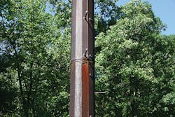
In the transmission industry, the use of weathering steel, also known as COR-TEN, began as early as 40 years ago. Many utilities prefer to use weathering steel because of its aesthetically pleasing brown, organic finish that helps poles to blend into wooded areas. It is also slightly lower in initial cost as a result of eliminating the need for galvanizing. The steel develops a patina, or thin protective layer of rust oxide, which gives the structure its rusty brown color.
For weathering steel to develop its patina properly, the utmost consideration should be given to the type of environment in which it will be installed. Exposure to moisture initiates the corrosion process, but a drying cycle is required for the oxidized layer to become a nonporous, protective layer. If the material is never allowed to dry or is exposed to continuous humid conditions, the patina will not stabilize and the steel will corrode.
Weathering steel originally was believed to be low maintenance; it was advertised and sold as an install-and-forget-it material. However, this is not the case. Routine maintenance is required on lines located where dense vegetation may grow up around the bases of structures, holding moisture and preventing proper formation of the weathering patina. Although American Electric Power (AEP) successfully uses weathering-steel poles on its system, one of its 20-year-old pole lines was showing signs of severe corrosion the utility had to address.
Initial Indication
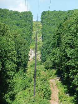
AEP has experienced the best results with weathering steel in its western service regions, where drier conditions provide adequate wet-dry cycles for the patina to develop. Different results occurred on the 138-kV Celanese-Peters Mountain line, located in western Virginia. The line runs 3.5 miles (5.6 km) between Pearisburg and Narrows, Virginia, and consists of 37 structures, 33 of which are direct-embedded weathering-steel poles. The route crosses densely vegetated, mountainous terrain and is subjected to humid conditions.
A storm-caused outage in early May 2013 prompted AEP to focus attention on the Celanese-Peters Mountain line. The utility’s transmission field services (TFS) crew, based in Bluefield, Virginia, quickly responded. A site investigation revealed the outage was caused by a tree falling onto the line, damaging the middle-phase davit arm on the north side of structure 12. However, that was not the only damage.
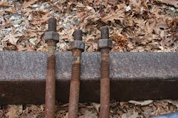
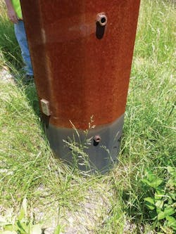
After removing the damaged arm bracket, severe corrosion was noted at the connection site around the bolt holes in the pole shaft wall. The weathering-steel bolts themselves were rusted and showed signs of cross-section loss. Severe corrosion also was observed at the base of the pole. The protective ground-line coating was peeling and flaking, exposing the pole shaft underneath.
TFS notified the transmission line engineering (TLE) and transmission line standards (TLS) groups in AEP’s Roanoke, Virginia, office. TFS replaced the damaged weathering-steel arm and bolts on the structure with a new galvanized-steel davit arm and bolts attached just below the original location. TLS decided to conduct a field inspection to determine the condition of this and other poles on the line. AEP retained ReliaPOLE Inspection Services Co. (RISC) to help perform the site inspections and provide a written report of its findings and remediation recommendations.
Initial Inspection
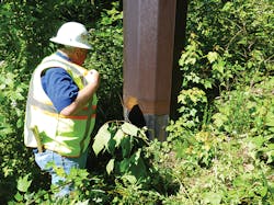
On May 30, RISC accompanied AEP staff to the site of the damaged structure 12. While on site, several other poles also were inspected, such as structure 14 — the farthest pole that could be accessed safely and easily because of the terrain and dense vegetation. Significant vegetation removal would be required to access most of the structures on the line. Such lush conditions held moisture close to the bases of the poles, contributing to the early deterioration of the structures.
Severe corrosion was observed at the ground line on all poles between structures 14 and 6. In some cases, ground sleeves were deteriorating severely. Structure 5 exhibited minimal corrosion at the ground line. Structures 1 through 4 were wood poles and not part of the inspection.
RISC took field measurements of the pole-shaft wall thicknesses on the corroded structures. Using an ultrasonic testing device, thickness measurements were taken at various locations above the ground-line protective coating and where the protective coating was flaking off at the ground sleeve. A cellulose-gel couplant was applied at various locations on the pole shaft, and then the ultrasonic testing transducer was engaged at these spots to get material-thickness readings.
The original thickness of the pole shaft walls was determined to be a nominal 0.25-inch (6.35-mm) thickness. Measurements taken on structure 12 ranged from 0.25 inches down to 0.18 inches (4.6 mm), which translated as a loss in material thickness up to approximately 30%. A few readings on structure 6 indicated a nearly 40% section loss.
Also noted, the top of the ground sleeves on many of the inspected structures were barely above ground line and some were completely buried. The position of the ground sleeves with respect to the ground could vary due to the holes being over-excavated at the time of construction, causing the poles to be set lower in the ground. The original detailed pole drawings for this line called for the use of two foot-long ground sleeves centered at ground line. This is an outdated specification that does not allow for much adjustment in the setting of the poles; 1 ft (0.3 m) easily can be lost because of hill slopes and variations in field conditions.
Another concern was pack-out, or pack rust, at the lap splices of several poles. The term pack-out refers to moisture gathering at joints, seams or holes and creating excessive rust oxide. As pack-out continues, steel thickness is sacrificed and the pole shaft weakens over time, threatening the structural integrity of the pole. Structures 11 through 14 showed pack-out issues during the site visit.
The level of corrosion observed at the davit arm connections on the remaining structures was minimal. RISC determined it was not as severe as the corrosion observed at the ground line or lap splices. RISC recommended AEP replace the weathering-steel through-bolts with new galvanized through-bolts as part of an ongoing maintenance program. The replacement of the bolts would include installation of new oversized plate washers. The time frame for the suggested work is over the next five years, as maintenance outages permit.
Ultimately, RISC determined pack-out corrosion was most critical to undermining the structural integrity of the Celanese-Peters Mountain poles. The added pressure from the pack-out at the lap splices could put too much strain on the long seam weld of the pole shaft, causing it to split. RISC recommended a follow-up inspection within six months to investigate the corrosion observed at these splices further.
Follow-Up Inspection
In November 2013, AEP and RISC conducted another site visit. The goal of this trip was to take a core sample of the steel just above the lap splice to determine whether the pack-out observed during the May visit was caused by moisture trapped inside the pole. The investigative procedure involved using a magnetic drill to core through the top ply of steel (female pole section) only. If moisture and rust were found between the two plies, it would be evidence moisture accumulated inside the pole shaft and was trying to weep out at the splice.
The inspection showed the underlying ply of steel (male pole section) was dry, clean and free from rust. The inside face of the core sample taken from the female section was also free from rust. The pack-out was determined to be external only and caused by moisture accumulating at the overlap of the splice. Ultrasonic testing readings showed no section loss of the pole wall.
Based on the favorable outcome of the pack-out inspection, RISC and AEP decided to shift focus to the corrosion issues at the ground line. RISC would return later to remediate the corrosion at the ground line.
Ground-Line Repairs
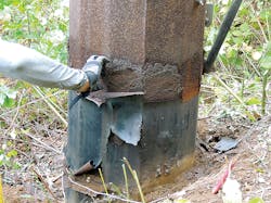
Structures 5 through 14 were repaired in October 2014, and structures 15 through 37 were completed in October 2015. Remediation involved excavating 2 ft (0.6 m) below the ground line, or until a solid ground-line protective coating was found, and then removing the damaged or loose coating from the base of the poles using a power grinder and a rolling wire brush.
The grinder smoothed the surface of the pole and removed the old, loose protective coating at the ground line. The wire brush scarified the surface to enable better adherence of a new protective polyurethane coating. Chemline’s Chemthane two-part polyurethane was mixed on-site and applied generously with a paint roller to 2 ft above ground line. It is estimated the application of the new coating will extend the life of the poles another 10 to 15 years.
Other Weathering Lines
An inspection of several other weathering-steel pole lines in AEP’s Virginia service territory did not exhibit the same corrosion issues experienced on the Celanese-Peters Mountain line. There are various reasons for the improved performance of the weathering material on these lines, but most important is they are not as old as the Celanese-Peters Mountain structures. Their long-term performance has yet to be determined.
AEP found poles installed on concrete piers experienced better performance at the base than direct-embedded poles. The ground-line protection on direct-embedded poles of another line was feathered, with a gradual transition from the bare portion of the pole to the coated portion at the base.
The original ground-line protection on the Celanese-Peters Mountain poles had a straight, taped edge, creating a ledge for moisture to accumulate and rust to develop. This eventually caused the coating to peel back and crack. Feathering the ground-line protection ensures the longevity of the coating and is now required on all of AEP’s direct-embedded galvanized-steel and weathering-steel pole details.
Improved Pole Detailing
AEP has incorporated improved standard pole details on new weathering-steel line designs. The utility has taken great effort to eliminate the infiltration of moisture inside the structures, as well as to minimize the accumulation of moisture at joints and connections. AEP has codeveloped modified details with input from its steel pole suppliers. Improvements include the following:
• Ground sleeve length increased from 2 ft to 4 ft (0.6 m to 1.2 m) to allow for more flexibility against variations in field conditions.
• AEP no longer uses weathering-steel bolts on projects.
• Through-bolted connections are discouraged except where holes are sleeved, to prevent water infiltration
• Through-vang connections are specified for arm brackets instead of bolt-through configurations
• Bottom pole sections are hermetically sealed
• Field drilling of weathering poles is prohibited.
Future Use of Weathering Steel
AEP still uses weathering steel in many of its service regions where conditions are conducive to its use and when it is required for aesthetic purposes. Before selecting weathering steel, consider the local environment in which the structures will be installed. It also is important to consider the additional detailing required to protect the structures properly from premature deterioration. Finally, a strong inspection and maintenance program is critical to the longevity of the structures.
Thomas J. Christy is a senior engineer with American Electric Power, where he has worked since 2011. He holds a BSCE degree from Ohio Northern University and is a professional engineer in the state of Ohio. Christy is a member of the American Society of Civil Engineers and has previously presented on this topic in the Managing Aging Infrastructure session at the 2015 Structural Engineering Institute/ASCE Electrical Transmission & Substation Structures Conference held in Branson, Missouri.
