Overhead or Underground Transmission? That is (Still) the Question

For years, the electric utility industry has been questioning whether to use overhead or underground systems for transmission of power using high-voltage transmission lines. Issues driving this discussion range from aesthetics to audible noise and electromagnetic field exposure, to susceptibility and storm damage. It often has been noted that lower-voltage distribution networks are common in newer construction, and cities usually have no option but to use high-voltage underground systems to transmit bulk power. More recently, high-voltage overhead transmission lines have been implicated in starting wildfires. As a result, electric utility executives have promised to review policies for deciding whether to use overhead or underground power transmission systems.
There is also new discussion at the national level about power grid upgrades to support increased electrification. Given this background, it is important to revisit issues relevant to decisions on whether to use overhead or underground transmission. Utilities must understand specific issues to consider when evaluating the use of alternating current (ac) high-voltage cables for long-distance transfer of electrical power. These include issues related to both design and construction as well as the operation of these systems. Emphasis should be placed on challenges with the use of underground high-voltage ac lines to transmit bulk electrical power.
Environmental Siting
The environment in which a 100-kV or higher transmission line is to be placed may preclude (or at least make very difficult) either the installation of overhead or underground transmission. For example, long distances across deep water or restricted overhead space in urban areas may preclude the use of overhead transmission. On the other hand, mountainous or hilly terrain or wetlands may preclude the use of underground transmission. Once feasibility is determined, it should be noted underground cables take up less right-of-way than overhead lines and have less visual impact on the environment.

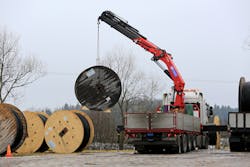
However, excavation for underground transmission can be disruptive and is not always easy. Underground obstacles must be considered. However, in recent years, horizontal directional drilling technology has mitigated some of these problems. Obstacles that may be encountered include bedrock near the surface, streams, railroads, other utilities, sanitary and storm sewers, streets and highways. All of these can add to the difficulty (and cost) of siting an underground transmission line. Once installed, the underground area must be safe from accidental contact by construction equipment, and vegetation must be managed to avoid roots and rodents from interfering with the system.
Finally, in any location, permitting, political constraints and factors such as archaeological sites may determine whether overhead or underground transmission must be used.
Material & Construction Costs
Overall, the cost of constructing a high-voltage underground transmission line varies from on the order of four times to on the order of more than 10 times the cost of an overhead transmission line. These costs include the generally more expensive underground cable compared to the cost of overhead conductors, materials associated with its burial in the earth (for example, installing the cables in ducts enclosed in concrete), and continuous excavation (or horizontal drilling) for underground transmission vs. poles, tower structures and foundations for overhead transmission.
In addition, underground transmission systems usually include several items that contribute to these higher costs. Relatively frequent splices are needed to join cable sections, because there are limits to shipping and weight restrictions on cable reels and to the tension a cable can withstand as it is pulled during installation. A concrete vault often is needed to house the underground splices because of their complexity, and they require careful craftmanship and quality control. Sheath bonding schemes also are implemented within the cable vaults. By contrast, splices for overhead transmission lines are relatively simple to install and require no special housing.
Underground lines are connected to overhead lines or substations by means of special termination structures. Porcelain or composite insulators or housings, often called potheads, contain the actual connections between the in-earth and in-air portions of the line, and care must be taken to prevent moisture ingress and manage electric field distributions where semiconducting layers and insulation are peeled back from the cable. Like splices, these termination enclosures require quality craftmanship to minimize the risk of insulation degradation.
In addition, it is common to place lightning arresters close to the terminations to protect the underground cable from overvoltage damage that can be caused by nearby lightning strikes. Sheath voltage limiters (SVLs) are arresters installed to protect against overvoltages between the underground sheath (concentric neutrals).
Finally, in pressurized gas or dielectric fluid-filled systems, pressurizing plants are required. All these additional items add to the cost and complexity of an underground system. However, cross-linked polyethylene (XLPE) transmission cable technology largely has replaced pressurized cable systems and made the maintenance of the transmission cable system less complex.
Electric Fields & Insulation
Generally, electric fields between the conductors of an overhead transmission line are much smaller than those between the electrodes of an underground cable. This is because the voltage between conductors a and b (for a given voltage class) is the same whether the transmission line is overhead or underground, while the electric field between the conductors is related to the voltage in the following way:
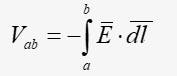
Hence, if the distance from a to b is shorter, as in an underground cable, the average electric field must be larger. Conversely, the average electric field for overhead lines is smaller. It is these electric fields that cause insulation breakdown and, hence, transmission line failure. Because overhead transmission lines have smaller electric fields in the space between conductors, it is possible to use natural air as the insulating medium.
However, underground conductors with larger electric fields must be placed in a medium that will not fail during normal operation of the transmission line. These include inert gases like SF6 or nitrogen, dielectric oil or solid dielectrics like XLPE. In the case of XLPE, high-quality manufacturing controls must be used to eliminate any contaminants or voids in insulation that could lead to local electric field enhancement, deterioration of the insulation and ultimate breakdown of the cable. These necessary insulating medium and manufacturing controls add to the cost of this type of cable.
Heating & Cooling
Any transmission line conductor will have finite electrical resistance and carry a high electric current. This results in heating of conductors because of ohmic losses (that is, i2 R losses) and losses due to hysteresis and eddy currents in steel pipes, sometimes used for mechanical protection of underground cables. Dielectric losses also contribute to the heating. Because of these heating effects, overhead and underground conductors are operated at temperatures much higher than the ambient temperature.
Therefore, cooling of the conductors (overhead or underground) is an important issue. Overhead conductors are cooled through thermal radiation from the air and convection from wind. Given these relatively efficient cooling mechanisms, the current-carrying capacity of a given overhead conductor (that is, its ampacity) generally is larger than that of a comparable underground cable conductor. Further, the maximum operating temperature for specialized overhead conductors varies near 100°C (212°F) to more than 200°C (392°F).
The less-efficient cooling of non-pressurized underground transmission lines is a more limiting factor in their operation because — absent a separate cooling system — all heat must be removed via thermal conduction through the materials (for example, soil, concrete and electrical insulation) in which the conductors that form the cable are embedded. Hence, the maximum current carried by underground conductors generally is more limited.
Further, maximum operating temperatures of underground cables are approximately 90°C (194°F), although short-term emergency ratings may be as much as 140°C (284°F). One additional issue designers of underground systems must face is preventing soil moisture from being removed. Moisture is needed to keep the thermal resistance of the soil constant to help cool the cables. In some cases, a separate cooling system may be needed to allow larger currents (and larger power transmission) than would be possible otherwise.
Environmental Risks and Reliability
Overhead transmission lines are subject to damage from lightning, tree falls, severe windstorms, excessive icing and earthquakes. In most cases, lightning only causes intermittent outages, given the lightning protection systems associated with these lines. However, damage from other environmental stresses may cause transmission line failures that require maintenance.
Underground transmission lines may be subject to lightning strikes, flooding and earthquakes as well as damage from human digging. The network of high-voltage overhead transmission lines tends to be quite reliable. In fact, because of the interconnected nature of the transmission system and requirements that it operate in the presence of a single or often multiple contingencies (that is, the loss of one or more transmission lines), most transmission line failures do not result in noticeable consumer outages. More specifically, according to one Australian study, well-designed overhead transmission lines operating at voltages greater than 110 kV have low total outage rates of about 1 per 100 km (62 miles) of line per year.
Consistent with this, a presentation from NEI Electric Power Engineering Inc., posted on the New Hampshire Public Utilities Commission website, states that transmission line failures are the cause of only about 2% of consumer power outages. The remainder are a result of subtransmission and distribution facilities. Statistics show underground transmission lines are more reliable than overhead lines, but the time and cost to fix underground lines is much more than overhead lines. Estimates of repair rates for XLPE transmission cables from the Wisconsin Public Service Commission indicate the chance of an issue on underground cable requiring repair is 1 out of 1600 per km per year. A similar rate for pipe-type cables is 1 out of 500 per km per year.
Given appropriate equipment, identifying the approximate location of a fault on either an overhead or an underground transmission line generally is generally a straightforward process. However, while locating the specific site of a fault on overhead transmission lines can be quick because the components are visible, the same process for underground transmission lines is much more difficult and time consuming because it can require opening vaults and excavation before inspection. Nevertheless, some newer technologies such as fiber-optic acoustic sensing are leading to more efficient detection of faults on underground cables.
The real difference between overhead and underground transmission comes in the duration of outages. While outages on overhead lines usually last less than a day, the typical duration of an XLPE outage is five days to nine days. The specific duration of outages varies widely, depending on the circumstances of the failure, availability of parts and skill level of available repair personnel. A faulted cable section must usually be abandoned or replaced. The latter requires replacement of the entire section between bounding vaults.
Line Life Expectancy
Overhead transmission lines have been known to survive without replacement for nearly 100 years. In the past, underground transmission lines generally had shorter life spans for a variety of reasons. High-pressure fluid-filled (HPFF) cables had mechanical issues with splices. However, these were corrected and installations from the 1960s continue to operate with no need for wholesale replacement of the cable. XLPE cables had early problems associated with moisture ingress and higher temperatures. Again, these were corrected and XLPE systems installed in the late 1980s, early 2000s and 2017 at respective voltages of 230 kV, 345 kV and 500 kV are still operating at the time of this writing.
According to the Wisconsin Public Service Commission, the assumed life of underground pipe-type or XLPE cable is about 40 years, although this number appears to be related more to financial issues rather than hard data from experience. Further, this number might increase as experience with installed systems accumulates.
One possible method for quantifying this issue further is to examine the warranty given to power cables by the manufacturer. Extrapolating service life accurately may not be possible, but warranties can provide an idea of how long companies are willing to stand by their product.
External Electric & Magnetic Fields
As mentioned previously, electric fields are related to voltage. Higher voltage produces stronger electric fields. Electric fields of underground cables above the earth are (at least partially and usually nearly completely) shielded by the cable neutral and other metallic layers, concrete and soil. Hence, when all shielding is considered, electric fields in accessible locations generally are not an issue with underground transmission lines.
However, electric fields can be substantial in the vicinity of overhead transmission lines and must be managed according to utility policy or local regulations, where they exist. Magnetic fields are created by current and not shielded by typical earth material. The strength of the magnetic field from a single conductor increases as conductor current increases and decays as the inverse distance from the conductor. If equal and opposite parallel currents are located close together, the magnetic field is partially canceled and decays as the inverse square of the distance from the two currents. The closer the spacing between the currents, the more the cancellation.
Generally, underground transmission lines produce lower magnetic fields than overhead transmission lines because the underground conductors are placed closer together. However, it is possible to access points close to the underground conductors and, at these locations, the magnetic field may be larger than that of overhead conductors because of their proximity. Underground lines enclosed in steel pipe can have significantly lower magnetic fields than overhead lines or other kinds of underground lines because the steel pipe has magnetic shielding properties that may further reduce the field produced by the conductors.
Coming Up
Part two of this two-part article series will explore electrical operation issues. These occur primarily because typical ampacity ratings preclude the use of cables at loadings at or near surge impedance loading. This is because the surge impedance of cables is typically on the order of ten times that of overhead lines resulting in very large surge impedance loading. Hence, for underground lines the reactive power consumed by cable inductance will never be sufficient to compensate for that supplied by cable capacitance. This leads to both hard and practical length limits for underground transmission lines, especially at higher voltages.
Dr. Robert G. Olsen is professor emeritus in the School of Electrical Engineering and Computer Science at Washington State University. He received his Ph.D. and MSEE degrees from the University of Colorado Boulder in 1970 and 1974, respectively, and his BSEE degree from Rutgers University in 1968. He has been with Washington State University since 1973. His other positions included senior scientist with the Westinghouse Georesearch Laboratory in Colorado; NSF faculty fellow with GTE Laboratories in Massachusetts; a visiting scientist with ABB corporate research in Sweden and the Electric Power Research Institute (EPRI) in California; and a visiting professor with the Technical University of Denmark. His work has been featured in approximately 250 refereed journals and conferences. He is one of the authors of the EPRI AC Transmission Line Reference Book — 200 kV and Above (EPRI, 2005). Olsen is an honorary life member of the IEEE Electromagnetic Compatibility (EMC) Society. He also is a past U.S. National Committee representative of CIGRE Study Committee 36 (EMC) and a past chair of IEEE Power & Energy Society ac fields and corona effects working groups. In addition, he is a past associate editor for the IEEE Transactions on Electromagnetic Compatibility and Radio Science.
Jon T. Leman ([email protected]) is an electrical engineer with over 20 years of experience in AC and DC overhead and underground transmission line design and power system studies. He is currently the owner and principal engineer of Power Electromagnetics Consulting, PLLC and a partner at Electric Utility Design Tools, LLC, a provider of transmission line design software. Leman earned his Ph.D. degree in electrical and computer engineering from Washington State University and his MSEE and BSEE degrees from the University of Idaho. His technical interests include electromagnetics, power system transients, equipment failure investigation, numerical methods, insulation coordination, and power system planning. The focus of his doctoral research was the application of electromagnetics to optimize high-voltage transmission line design. He is a member of CIGRE and a senior member of IEEE.
About the Author
Robert G. Olsen
Robert G. Olsen ([email protected]) received the B.S.E.E. degree from Rutgers University, New Brunswick, NJ, USA, in 1968, and the M.S. and Ph.D. degrees from the University of Colorado, Boulder, CO, USA, in 1970 and 1974, respectively. Since 1973, he has been with Washington State University, Pullman, WA, USA. Other positions include Senior Scientist with Westinghouse Georesearch Laboratory, NSF Faculty Fellow with GTE Laboratories, and Visiting Scientist with ABB Corporate Research and EPRI. His research interest is application of electromagnetic theory to high-voltage transmission systems. He has nearly 100 publications in refereed journals. He is one of the authors of the AC Transmission Line Reference Book—200 kV and Above (EPRI, 2005). Dr. Olsen is an Honorary Life Member of the IEEE Electromagnetic Compatibility (EMC) Society. He is also past USNC representative to CIGRE Study Committee 36 (EMC) and Past Chair of the IEEE Power Engineering Society AC Fields and Corona Effects Working Groups. In addition, he is also the Past Associate Editor for the IEEE Transactions on Electromagnetic Compatibility and Radio Science.
Jon T. Leman
Jon T. Leman ([email protected]), P.E., is a principal engineer with the consulting firm POWER Engineers, Inc. where he specializes in AC and DC overhead and underground transmission line electrical design. He also is co-owner of the software company Electric Utility Design Tools, LLC. Leman earned his Ph.D. degree in electrical and computer engineering from Washington State University in 2021 and his MSEE and BSEE degrees from the University of Idaho in 2010 and 2001, respectively. He taught courses in physics and electrical engineering for the U.S. Navy from 2001 to 2005. In 2005, he joined POWER Engineers. His technical interests are electromagnetics, power system transients, equipment failure investigation, numerical methods, insulation coordination, and power system planning. The focus of his doctoral research was application of electromagnetics to optimize high-voltage transmission line design. He is a member of CIGRE and a senior member of IEEE.