The need for electric power is rapidly increasing in the developing world. Power sources close to consumption centers have already been harnessed, and present efforts are exploring ways to generate and move power from further away, especially sources of renewable energy. Developing countries such as China, India and Brazil have large populations and are modernizing quickly, but closing the gap with the developed world will require a large amount of electric power.
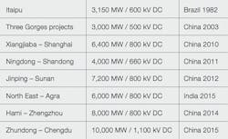
HVDC is the most environmentally friendly and economical way of transmitting large amounts of electric power. Compared with AC, DC transmission needs much narrower right-of-ways, while higher voltages reduce both electricity losses and the cost of building large-scale power lines. As generation takes place further and further away, higher and higher transmission voltages are required. The highest DC transmission voltage has almost doubled during the last decade ➔ 1.
1 Some of ABB's key HVDC projects
The swift pace of economic development in certain regions has meant the time to develop equipment to support higher transmission voltage levels has been very short. Chinese customers in particular have pressed for rapid development and delivery of the first projects using UHVDC technology, driven by the immediate need for transmission assets. Compounding the pressure, stringent reliability requirements are a prerequisite of these very large transmission projects.
Transmission basics
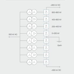
The State Grid Corporation of China put the world`s first 800 kV DC transmission system into commercial operation in 2010. It is a 2,000 km long power line with a capacity of 6,400 MW, generated by a large hydropower plant in Xiangjiaba and transmitted to Shanghai. The AC to DC converters are built as ± 800 kV double circuits with eight series-connected, six-pulse converters. The transformers are single phase, two-winding units. In total, 24 converter transformers are needed at both the sending and receiving ends.
Depending on the position of the transformers within the converter, four different designs are needed with different DC voltage ratings (800, 600, 400 and 200 kV) where the transformers connected to the uppermost and lowermost bridges had to be built for the highest DC potential ➔ 2.
2 Basic arrangement of transformers and converters
For the Xiangjiaba to Shanghai project ABB designed and built transformers for the receiving station. The transformers for the higher voltages were designed and manufactured in Ludvika, Sweden. The remaining units were manufactured by ABB's partners in China.
System requirements for converter transformers
The basic function of the converter transformer is to adjust the line voltage of the AC side to the HVDC transmission voltage. In addition, it must fulfill other specific requirements, including:
- A galvanic separation between the DC and AC systems
- Specified short-circuit impedance
- High content of current harmonics
- Large range of voltage regulation
In conventional AC/DC converters, the transformer acts as a barrier to prevent DC voltage from entering the AC network. One of the transformer windings is connected to the AC side, which is also called the line-side winding. The other winding is connected to the converter valves, called the valve-side winding.
DC voltage results in additional demands on the insulation structure in comparison to AC voltages. After long and dedicated research and development, ABB has developed a successful insulation system suitable for the highest transmission voltages for AC as well as DC.
The design of the valve is such that the rate of current increase must be controlled when the valve starts carrying current. The rate of increase largely depends on the transformer reactance, which also has to be fulfilled within narrow limits for two individual transformer units.
The high content of current harmonics requires special attention be paid to controlling additional and stray losses in the transformer, when it comes to total losses and the risks of local overheating in the windings and metallic components exposed to stray flux from windings and internal current carrying leads.
In order to optimize the reactive power needed for the operation of the converter, depending on load variations the system designer generally specifies a large range of voltage ratio variation between the line and valve sides.
Pioneering work
In the late 1970s, ABB did pioneering work in this area when the first set of transformers for 600 kV DC transmission was delivered to the Itaipu HVDC project in Brazil.
The transformer concept used for Itaipu has been a template for most HVDC converter transformers: a single-phase design, with two wound limbs and two outer limbs for the return flux. The windings are arranged concentrically with the valve winding on the outside. The line winding is divided into two coils – the one for the tapped part is located closest to the core, followed by the nontapped section. This arrangement is beneficial for the topology of the valve-side, which requires AC as well as DC insulation.
The basic Itaipu concept has undergone continuous improvements, such as valveside bushings protruding directly into the valve hall. Eliminating the need for separate bushings between the transformer terminal and the interior of the valve hall helped to reduce the cost and complexity of station layouts. In addition, step porcelain bushing housing was replaced by composite material, and within the bushing compressed gas replaced oil. These new materials remove the risk of disastrous consequences in the event of a bushing failure.
AC and DC stresses
The stress patterns for AC voltage between two electrodes are fairly straightforward. The stresses of different materials in combined insulations depend primarily on the permittivity of the individual materials. In order to reach reliable operation, the stresses for each of the insulating materials must not exceed a recommended value. The insulation structures in an HVDC converter transformer are built up from cellulose-based solid insulation and mineral oil as an insulation and cooling medium. The free distance in a liquid insulating material must be controlled by intermediate insulation barriers to reduce the risk of abnormal voltage breakdowns. In short, predicting stress distributions caused by AC waveforms is straightforward, and the material parameters are stable under different operating conditions. The physics and its engineering application are well-known, at least for moderate voltage levels.
The stress pattern for a DC voltage applied between electrodes will have a similar distribution in the initial phase after the application of the voltage. After the initial state, the electric stress pattern goes through a transient state, finally ending up in a steady state, often after several hours. In contrast to AC, the material parameters that govern behavior under DC stress display larger variation and the background physics is very complex. Variations of material parameters and design have large consequences for the electric stress occurring inside the transformers, and this is why insulation structures have to be designed and manufactured with great care to achieve a reliable result.
ABB has developed the means to accurately measure stresses in models of the insulation systems used in HVDC converter transformers.
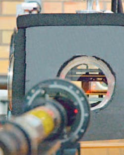
3 Measurement setup
Electric stress in more complex insulation structures can be modeled and measured using the electro-optic Kerr effect. Polarized light passing through transformer oil changes its polarization state depending on the electric stress applied. Detection of the phase shift between light components parallel and perpendicular to the electric field allow measurements of the magnitude and direction of the electric field. The low numerical value of the Kerr constant of transformer oil, and fairly moderate field stress in the fluid phase of the insulation places stringent requirements on the measurement system to achieve sufficient accuracy to measure magnitude and direction of the electric field ➔ 3.
The Kerr cell measurement has given ABB valuable information about the stress distribution in multibarrier insulation systems used in high-voltage power transformers in transient as well as steadystate conditions. For a more accurate analysis the distribution of space charges has to be considered, especially for a barrier system with small ducts between the individual barriers. The traditional method of resistive steady-state distribution has important limitations, and reliable insulation structures cannot be developed based only on such a theoretical method. However, calculation models based on true charge transport behavior developed by ABB and calibrated by real measurements are the basis for all design rules concerning reliable insulation structures for all ABB converter transformers today.
The challenge of UHVDC
Although ABB had all the basic knowledge in-house, it was also necessary to acquire hands-on experience with the characteristics of vital components in the transformers, as well as external connections, particularly on the valve side. For that purpose, a full-scale test model was built, complete with tank, windings, internal connections and valve-side bushings for the development of equipment for use in both 800 kV and 1,100 kV DC transmissions.➔ 4. Over time, models were exposed to very demanding operational and test conditions to fully demonstrate reliable performance. Special attention was paid to components with complicated geometry, like windings and the connection between the valve winding and bushing. An intricate balance between solid and fluid insulation has to be achieved in the design of the transformer insulation.
4 800 kV converter transformer
The HVDC bushing was another component needing special attention. As its air side enters the valve hall, it is essential that a breakdown not lead to fire or damage from shattered pieces of the bushing.
For that reason, the insulation system around the bushing lead is a condenser body, and the space between the body and the cylinder-shaped insulator is filled with compressed gas. Silicon sheds are extruded on the tube outside to permit indoor or outdoor use.
Scientific advances have not only been made in transformer insulation, but also bushings. Challenges similar to those in oil and cellulose insulation also exist in air insulation systems. An ABB innovation enabled the electric field to be measured on the surface of an insulator on the bushing of an HVDC transformer. Simulation models are calibrated by actual measurements, and special phenomena are integrated into the bushing design.
Tests
A transformer is subject to delivery tests after it is manufactured, assembled and installed on site. These tests are for verification of dielectric and operational requirements set forth in the unit`s specifications, as well as the internal ABB quality assurance program.
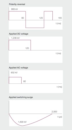
Compared with a conventional power transformer in the AC network, an HVDC converter transformer must be tested for the ability of valve-side windings to withstand DC voltages. In operation, the valve windings are exposed to an AC voltage and a superimposed DC voltage. A DC transmission must be able to handle the fast transition of power from one direction to the other. Such transitions also mean a switch in converter polarity, from positive to negative, and vice versa ➔ 5.
5 Additional dielectric tests for the valve winding together with corresponding voltages and durations
Operation with continuous DC voltage, superimposed AC voltage and DC polarity reversal will be reflected in additional dielectric tests of the valve-side windings; tests with DC voltage, tests with AC voltage and tests with switching surge voltage are in accordance with IEC standards. All four types of test are considered to be nontransient, with a uniform voltage along the valve winding. For that reason, the two external terminals of the winding are connected together and the voltage is applied to the two terminals simultaneously.
During the test with applied DC voltage, the level of partial discharge is measured. During the transient period after the application of voltage, there may be occasional charge movements within the insulation system. These movements give rise to a noticeable partial discharge signal on the valve-side terminals. The phenomenon is well known and recognized in current standards. The industry has therefore accepted an upper limit on the number of occasions such bursts of partial discharge can take place during the tests. Furthermore, the frequency of bursts must diminish during the course of the test.
The world needs UHVDC
Driven by economic growth, demand for power and the need to efficiently integrate renewable power generation, it is clear from developments in AC networks that UHVDC will have a major role to play as power systems evolve. The expansion of this role is also clear from the interest in extending the capabilities of UHVDC transmission in the recent years. Given UHVDC's very high ratings, it is essential that these valuable assets operate safely, reliably and efficiently.
ABB has the proven tools and expertise needed to design and manufacture reliable UHVDC converter transformers. This solid technology background ensures that even in the fast-developing UHVDC area, customers can be sure that ABB equipment is designed, tested and built to the highest standards of operational stability. Of the UHVDC projects awarded globally, ABB is by far the largest supplier and is determined to maintain this lead with further advances in the technology ➔ 6.
|
6 Success story: the world's most powerful UHVDC converter transformer ABB has successfully developed and tested a 1,100 kV UHVDC converter transformer, breaking the record for the highest DC voltage level ever achieved, which means more electricity can be transmitted efficiently over even longer distances. The Xiangjiaba-Shanghai link commissioned by ABB is the world's first commercial 800 kV UHVDC connection ➔ picture 2 on page 8. It has a capacity of 6,400 MW and at just over 2,000 km is the longest power link of its kind in operation. The new 1,100 kV converter transformer technology just tested will make it possible to transmit more than 10,000 MW of power over distances as long as 3,000 km. Higher voltage levels enable the transport of larger amounts of electricity across very long distances with minimal losses, using HVDC technology. Converter transformers play a critical role in HVDC transmis - sion, serving as the vital interface between the DC link and the AC network. The development of 1,100 kV transformers addresses several technology challenges, including the sheer size and scale of the units, electrical insulation including bushings and thermal performance parameters. UHVDC transmission is a development of HVDC, a technology pioneered by ABB more than 50 years ago, and represents the biggest capacity and efficiency leap in more than two decades. |
So what is the next step for UHVDC? China has clearly expressed an ambition to achieve even higher DC transmission voltages. That ambition has materialized in an R&D program for 1,100 kV UHVDC transmission, which of course requires a range of different equipment, including converter transformers built to support these record-breaking UHVDC transmissions. Rising to the challenge of these very ambitious development plans, ABB was the first to qualify HVDC converter transformer technology at the 1,100 kV voltage level as well, but how that came about in detail is a story for another day – the continuing story of ultra-efficient, ultrahigh-voltage direct current electricity transmission.
Thomas Freyhult
Mats Berglund
ABB Power Products, Transformers
Ludvika, Sweden
[email protected]
[email protected]
The authors acknowledge the contribution to this article of the late Åke Carlsson, ABB Senior Transformer Specialist.

