HVDC Link Increases Interconnection Capacity
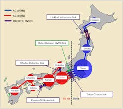
The extra-high-voltage transmission systems in Japan are interconnected to ensure efficient operation and provide mutual power transfer when needed at peak demand. The power frequency of the transmission system in the eastern region of the country, operated by the Tokyo Electric Power Grid Co. (TEPCO PG), is 50 Hz and in the western region, operated by the Chubu Electric Power Co. (CHUBU PG), is 60 Hz.
The following two primary considerations led to a decision to construct a new high-voltage direct-current (HVDC) link and frequency converter facility by 2020 between the two regions to increase the existing interconnection capacity from 1200 MW to 2100 MW:
To increase the power transfer capacity in the event of a large-scale disaster, like that of an earthquake in East Japan in 2011
To consider the increasing generation from renewable energy sources, namely photovoltaics (PV) and wind farms, which has led to brisk trading activities on Japan’s deregulated energy market.
To interconnect the two different frequency systems through the conversion of alternating current (ac) to direct current (dc), the new HVDC link design was based on line-commutated conversion (LCC) HVDC power transmission technology for economical and operation and maintenance (O&M) reasons.
Project Construction
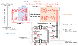
The project entailed constructing one converter terminal on the 50-Hz side in the existing Shin-Shinano frequency converter station and a new Hida frequency converter station on the 60-Hz side. The new 900-MW Hida-Shinano HVDC link has one circuit of a bi-pole on an approximately 90-km (56-mile) long overhead transmission line, with dedicated metallic return conductors for each pole grounded at the 60-Hz side converter station and not grounded at the 50-Hz side converter station. The HVDC control system is designed with the 50-Hz side as the master converter station. All control commands are communicated through this master station.
On the 60-Hz side of the Hida-Shinano HVDC link, the system voltage is stepped down from 500 kV to 154 kV by the step-down transformers. The converter transformers and ac harmonic filters are connected to the 154-kV bus bar for each pole. By stepping down the voltage of the converter system to 154 kV, it is possible to lower the insulation coordination level of the converter transformers and ac harmonic filters, making these components more compact.
One of the features not installed in the Hida converter station are shunt capacitors. Instead, the ac harmonic filters are configured in two groups for redundancy, so one of the ac harmonic filter groups act as the shunt capacitors. The reason for installing two groups is to provide continuous operation in the event of a failure of an ac harmonic filter. Furthermore, the shunt reactors switch during the non-conducting state or low-power operation, and the auxiliary power supply systems are connected to the tertiary circuit of the step-down transformers.
The contract for supplying the Hida converter station equipment was awarded to Hitachi ABB Power Grids in 2013. The company made efforts to optimize the system by taking into consideration their knowledge of the extreme climate conditions experienced at the converter station location. Ambient temperatures can range from -300°C to 350°C (-508°F to 662°F) at the site, which is some 1085 m (3560 ft) above sea level. The site typically experiences 2m (6.6 ft) of snow in the winter.
Construction and installation of the 200-kV HVDC overhead transmission line and the 50-Hz side Shin-Shinano frequency converter station, including an expansion of the converter station, was TEPCO PG’s responsibility. Construction of the entirely new Hida converter station on the 60-Hz side was CHUBU PG’s responsibility. The converter stations’ control and protection systems (C&Ps) were manufactured by Toshiba Corp. and Hitachi Ltd. on the 50-Hz and 60-Hz sides, respectively.
Civil works were required at both converter stations prior to the plant installations. Following both utilities’ completion of all the site works, multi-vendor integration testing started in the summer of 2018. This was followed by transmission system testing of the Hida frequency converter station, which went into commercial operation in March 2021.
Grounding Considerations
To comply with the traditional standard in Japan, a dedicated metallic return system was adopted for the existing HVDC systems to avoid adverse effects of the earth return current on structures located nearby and on magnetic compasses. However, CHUBU PG found — in the event of grounding faults on the Hida-Shinano HVDC overhead line — the effects of stray current, caused by injected dc current into the ground, required more detailed consideration.
When a ground fault occurred on the HVDC transmission line, the fault current mainly returned to the dc circuit by the earthing mesh and earth electrode of the 60-Hz side converter station. However, some fault current was being diverted to the ac transmission lines by the grounded neutral point circuits of the transformers at the neighboring substations. Also, it was diverted to the overhead grounding wire by the earthing mesh of the 60-Hz side converter station.
A scheme in which grounding mesh for dc and ac are separated was examined, but it was found impractical because of the limitations from the location of the converter station and available surrounding land space. CHUBU PG identified an alternative scheme whereby the neutral ground resistors (NGRs) were inserted to the main transformer connections at several locations in the possible current paths of the injected dc current in service on an existing HVDC in Japan. CHIBU PG studied this alternative grounding system and decided to install it at the Hida frequency converter station.
The maximum possible dc current injection at all positions was calculated with a special analysis model, with circuits inside the converter stations and the adjacent ac network — such as transformers and transmission lines, including their shielding wires and grounding resistance of the towers. These circuits were included to verify saturation of all the winding components, for example, power and instrument transformers.
Insulation and protection coordination also were studied with different neutral grounding resistor (NGR) combinations. It was concluded 5-ohm NGRs should be installed at the neutral grounding point of all power transformers installed inside the converter stations. By installing a 5-ohm NGR, current flowing through the overhead power lines was reduced by 73%.
The short-term current rating of the NGR was determined using fault current calculations for protection coordination and the continuous current rating, which took into consideration the zero-sequence current caused by system voltage imbalance among all possible power-flow scenarios.
As this HVDC system is connected to the ac network on the 60-Hz side by a T-branch connection to the 500-kV Etsumi trunk overhead transmission line, the power flow of the ac line may be much larger than the rated power of the HVDC system. If this occurs, an unbalanced voltage — including a zero-sequence component — is generated by large current flowing through the long-distance untransposed ac transmission line, and the continuous current of each NGR in the Hida converter station increases. In this project, the rated continuous current rating of the NGR in the Hida converter station is 162 A.
Multi-Vendor System Integration
The HVDC system is a multi-vendor system designed with the Shin-Shinano converter station as the master station, with the Hida converter station following it. The C&P of an HVDC system must be well coordinated, for example, with accurate timing coordination of start and stop signal transmission logic or protective operation control. Even a small disorder may cause significant disturbances in the ac network or damage the network equipment. After carefully defining details of the interstation telecommunication specification, such as the format and frame of the exchanged signals, a multi-vendor C&P system was established.
After testing on one end of the system in each manufacturer’s factory, the C&P system underwent combined testing to confirm system integrity before installation and commissioning at each site.
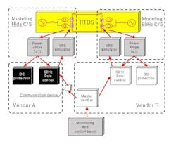
Major C&P panels and components for both ends also were collected in the Shin-Shinano converter station. The test setup was established by connecting control cables to the RTDS Simulator for testing the ac network and dc transmission line system together with a second simulator for the interstation communication link. Simulation cases were run to confirm the safe and stable operation of the HVDC link in start- and stop-operation modes and protection operations at fault events.
Project Timetable
The Hida frequency converter station is a 60,000-sq m (71,760-sq yd) site located in a mountainous region, so the planned construction timetable extended over a period of eight years, from 2013 to 2021. Completed in March 2021, the project was finished on time and within budget.
Since commissioning, the energy trading activity has been brisk and the station has been used multiple times. To date, there have been no reported technical issues.
New Expertise
Detailed consideration of the stray dc currents proved to be essential for the new HVDC overhead transmission line. CHUBU PG found and confirmed reasonable and practical solutions, such as the installation of NGRs following simulation studies with special models and parameter combinations. The utility also defined actions to take when a multi-vendor system is involved, by determining how to optimize the system configuration and overcoming the restricted installation area available in one converter terminal. Following all simulator testing, the commissioning test results proved very good.
CHUBU PG considers the expertise it acquired during the execution of this major project — its first HVDC project to establish an aerial interconnection between two transmission systems with different frequencies — will prove valuable for similar projects in the future.
Yoshinari Mochizuki ([email protected]) received his bachelor’s degree from the Meiji University in Tokyo in 1989, after which he joined the Chubu Electric Power Co. Inc. He has been engaged in system design applications of frequency converters and flexible ac transmission systems. Mochizuki, who now serves as general manager of the utility’s HVDC technical groups, is a member of the IEE in Japan.
Taizo Matsuda ([email protected]) was awarded a bachelor’s degree from Kagoshima University in Kagoshima in 2007, after which he joined the Chubu Electric Power Co. Inc. Since then, he has been engaged in system design of HVDC systems and flexible ac transmission systems (FACTS). Matsuda is now an assistant manager of the utility’s HVDC technical groups and a member of the IEE in Japan.
Satoshi Nakanobu ([email protected]) was awarded master’s degree from the Nagoya Institute of Technology in Nagoya in 2010 and joined the Chubu Electric Power Co. Inc. that same year. He has been engaged in the system design of the Hida frequency converter station and currently works as an assistant manager of the HVDC Technical Groups. Nakanobu is a member of the IEE in Japan and CIGRE.
For More Information
Hitachi ABB Power Grids | www.hitachiabb-powergrids.com
Hitachi | www.hitachi.com
RTDS | www.rtds.com
Toshiba | www.toshiba.com
Fig.1 Overview of transmission system in Japan (except for Okinawa).
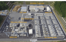
Fig. 2 Aerial view of commissioned Hida frequency converter station.
Fig. 3 System overview of Hida-Shinano HVDC link.
Fig. 4 NGRs installed to reduce stray dc current at grounding faults on HVDC overhead line.
Fig. 5 RTDS Simulator test in field.
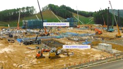
Fig. 6 Hida frequency converter station under construction in August 2018.
About the Author
Yoshinari Mochizuki
Yoshinari Mochizuki ([email protected]) received his bachelor’s degree from the Meiji University in Tokyo in 1989, after which he joined the Chubu Electric Power Co. Inc. He has been engaged in system design applications of frequency converters and flexible ac transmission systems. Mochizuki, who now serves as general manager of the utility’s HVDC technical groups, is a member of the IEE in Japan.
Taizo Matsuda
Taizo Matsuda ([email protected]) was awarded a bachelor’s degree from Kagoshima University in Kagoshima in 2007, after which he joined the Chubu Electric Power Co. Inc. Since then, he has been engaged in system design of HVDC systems and flexible ac transmission systems (FACTS). Matsuda is now an assistant manager of the utility’s HVDC technical groups and a member of the IEE in Japan.
Satoshi Nakanobu
Satoshi Nakanobu ([email protected]) was awarded master’s degree from the Nagoya Institute of Technology in Nagoya in 2010 and joined the Chubu Electric Power Co. Inc. that same year. He has been engaged in the system design of the Hida frequency converter station and currently works as an assistant manager of the HVDC Technical Groups. Nakanobu is a member of the IEE in Japan and CIGRE.
