Distribution Line Capacity Optimization for AC Microgrid
Introduction
Availability of electricity has greatly affected the livelihood of human beings, enhancing their quality of life. However, the geographical penetration of electricity has been more challenging with respect to the value proposition economic benefits. To extend the reach of electricity into geographically diversified locations with sparse population, portable sources of renewable electricity generation such as solar panels, biomass, fuel cells, wind and micro-hydro turbines, and so forth, have been innovated with most advanced controls and applications. Rapid development in the integrated chips and embedded controller has also boosted the control application for various sources which were available with limited implementation because of the safety regulation and fault prevention of the connected equipment. Development in the field of information and communication technology has supported adaptive infrastructure growth to support the microgrid, while urbanization and its impact on infrastructure have uplifted quality of life. Improvement in power generation technology has boosted the mobility of power generation at a low scale revenue development model for the microgrid into a sustainable source of power at rural and peri-urban areas. The decrease in the cost of power generation has also urged inverse infrastructure development for power distribution networks.
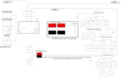
Fig.1: Basic layout of ring type microgrid
Basic Layout of Microgrid
Most of the contemporary grids are built in a radial fashion with only one possible line for specific consumption and generation connected to the grid. This layout (as depicted in Fig. 1) represents a microgrid, where generation is done at the center and power is distributed throughout the village. The generating station is at the middle of the grid and the loads are geographically distributed around the generation center without interconnecting individual lines (Line 1, Line 2 and Line 3). If any terminations of lines occur near the other line, then they can be merged to form a ring topology. In case the generating station is near the termination of any line, the lines can be connected with the help of directional relay. However, short circuit currents are larger, and protection is more complicated in ring-shaped distribution lines because of two power flow directions. Mesh grid is an electrical network with multiple alternative connections between nodes. An insulated cable system is a good alternative to a bare conductor system, because LV and MV distribution lines minimize pilferage and line outage resulting in better availability and reliability. Most common types (as presented in Table 1 below) of insulated overhead cable systems across the world are as follows:
Table 1: Types of insulated overhead cable systems
Practical Experiences
Case study of an ac microgrid is elaborated as follows for an overview of distribution line optimization:
Husk Power system installed a couple of hybrid microgrids with generation sources of biofuel (Husk) and solar photovoltaic (PV) systems at peri-urban areas of Bihar, India. The grid was supposed to cater to a load for 200 households and shops since the utility was present but with intermittent supply. 24x7 electricity access was critical, especially at dusk, since the village was also the town center for the hamlets nearby. The distribution network laid followed the standard of Rural Electrification Corporation, India, since the bulk of power being transmitted was enough to use the ABC cable (25 sq mm by 3 + 16 sq mm by 1 sq mm) for the distribution. The hardware and pole line fittings were also conventional. The poles had distribution box and energy meter mounting arrangement with appropriate IP to prevent any non-technical losses. Deploying the microgrid was comparatively challenging because the presence of the grid increased the right of way (RoW) issues, and cable stringing across the line.
Developments of cost-effective hardware capable of being mounted on walls were used. The cables had comparatively lower cross sections of 6 sq mm double cores. Hence, they used 4 mm GI wires as messenger cables which could be used for a span of 30 to 40 m. Hardware was portable and could be transported on head load. Application features of the hardware included:
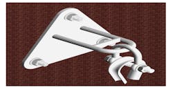
- Triangular wall bracket: It is an assembly arrangement used for cable mounting in distribution lines as presented in Fig. 2 below. It is primarily used for places where pole and hardware accessories mounting is difficult because of RoW issues and cost constraints. This bracket is mounted on the walls with the help of anchor bolts and can be used for carrying the load of anchor bolts. These are designed to carry both tension as well as suspension assembly.
Fig. 2 Schematic of triangular wall bracket
Fittings are changed for suspension and tension type and are described below:
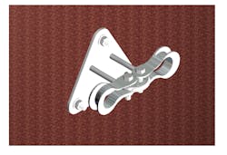
- Suspension assembly arrangement: This suspension assembly consists of triangle bracket, D-shackle, and thimble helical grip as shown in Fig. 3. It is mainly used to support the cable in between, to carry and distribute the load evenly. The D-shackle is fitted with the thimble, which supports the helical grip used to grip the GI wire.
Fig. 3 Suspension assembly arrangement
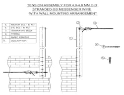
- Tension assembly arrangement with wall bracket: This arrangement is mainly used at the terminating points or at places where tension is required to carry the cable while maintaining the sag (as depicted in Fig. 4). The thimble is attached to the wall bracket by means of a nut and bolt to support the messenger wire.
Fig. 4 Tension assembly arrangement with wall bracket
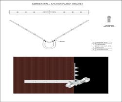
- Corner bracket: These brackets are designed to be used at the corner of the house or buildings to bend the line at 90°. Likewise, they are used to eliminate a pole to mount a wire at that point as given in Fig. 5. This process curtails the cost of a pole and simultaneously supports the wire mounting. It supports tension assembly and can also be used for dead end fittings.
Fig. 5 Corner wall anchor plate/ bracket
- Cable lashing rod: It is used to bind the GI messenger wire which acts as a strength member and electrical cable together. It covers a wider section of the cable, thereby distributing the load on the cable and the GI wire. Lashing clips are suitable for cables with bigger cross section, and the lashing rod can bind multiple cables with a thinner gauge. In lashing clips, all steel clamps securely attach two lashing wires or a ground wire on strand, and two grooved plates fit on opposite sides of the strand. Helical shaped lashing rods accommodate different cable sizes.
- Road cross wall bracket: Road cross wall bracket is a simple design and arrangement made from angle, eye bolt and stringing accessories to carry the cable along the walls and then raise it 2 to 3 m in order to cross the road and transfer the cable on other side of the road (as shown in Fig. 6). It is a cheaper solution for the microgrid and can be used where the roads are narrow and mounting of poles is extremely difficult.
Fig. 6 Road cross wall bracket
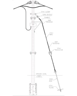
- Sectional pole and its assembly: Microgrid deployment is feasible where the reach of the conventional grid is either very difficult or extremely expensive. To overcome site transportation issues, number of poles can be reduced, although they are important parts of overhead lines. Sectional GI poles overcome these issues and can be easily fabricated from tubular pipes of different diameters welded with flange to fix two different sections together with nut and bolts. Base of steel poles can be fixed with the concrete mixture and can be rooted deeply, gripped with the help of bars drawn into the bore through the holes in the poles. Poles accessories can be mounted easily on the poles to string the distribution lines cables, and stays can be fixed on it as portrayed in Fig. 7 below.
Fig. 7 Pole mounting arrangement
- Distribution box: These boxes are majorly required for the microgrid since households are densely spread near the distribution lines and power requirement is quite high. As a result, higher current rating cables are required. These boxes generally accommodate bus bars and allow in-catering service connection to bunch of houses. It helps isolate the grid with a group of users which further eases maintenance. Ferruling makes it very effective to debug faults. A distribution box also makes it very convenient for new service connections. Its design should be such that it can be mounted on poles as well as on walls.
- Wall clamps and service lines: These are brought to households with the help of anchor wall plugs which can draw more than one service connection for households nearby. Service lines can travel on the distribution line path and can be drawn perpendicularly where the households are on the distribution path; but it should be kept away from the distribution box.
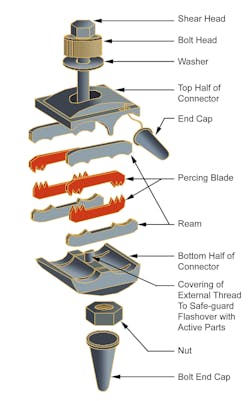
- Insulation piercing connectors: One of the most important components of LV - ABC system is the insulation piercing connector. It is by far the most critical component and a fitting of poor design or workmanship is doomed to be the weak link of the system. Insulation piercing is a technology that has evolved over a period of more than three decades and in some ways it is still evolving. It progressed from a design where both run and tap conductors were stripped and subsequently insulated by using a thermoplastic rigid cover with IP 23. It progressed to connectors that pierced the main, requiring only the tap to be stripped. Rigid covers gave way to flexible material being used for covers which would not break in cold climates (as portrayed in Fig. 8).
Fig. 8 Insulation piercing connector assembly
Conclusion
Microgrid with DERs is becoming an inevitable part of present distribution systems. The system was a three phase ac system with no major changes in the hardware compared with the conventional system with distribution capacity of 20 to 30 kWp to serve the 200-300 households. The architecture, in fact, used a few mechanisms to avoid non-technical losses. This optimization initiative encourages renewable generation investors to focus on profitable grid tied power systems tailored for large utility scale and smaller peri-urban implementations.
About the Author
Dharmbir Prasad
Dr. Dharmbir Prasad is an assistant professor at Asansol Engineering College, India.
Sushri Mukherjee
Sushri Mukherjee is pursuing master of technology in Power System at Indian Institute of Technology Delhi, India. Previously, she was working as a research and development engineer at Supreme & Co. Pvt. Ltd., India.
Md. Irfan Khan
Md. Irfan Khan is regional manager-South Asia for Supreme & Co. Pvt. Ltd., India. Previously, he was a regional manager for Supreme T&D Co. Ltd., Thailand.
Harish Agarwal
Harish Agarwal is CEO of Supreme & Co. Pvt. Ltd, director of Web Spiders (I) Pvt. Ltd and director of Thailand based company Supreme T&D Co. Ltd. He is also currently serving IEEMA as a president and vice president of CIGRE India.

