Today I’m going to give you a high-level overview on IEC61850 basics. I know, you have questions: What is 61850, what can it do and how can it help me in my substation? These are great questions. And hopefully in this article I will answer at least some of them. Fair warning, this article, and any future 61850 articles by me, will be based on my experience from actually installing Digital Smart Substations (DSS), which use 61850 to some extent. Note on what experience means: set scope, oversee design, set relay/switches/SCADA, commission & test system and, lastly, train team members on how it works.
The intent of this article is to provide a quick, high-level review of the most common aspects of IEC61850 from a practical standpoint. Second goal, make it fun and easy to read. Goal number three, get you looking into using IEC61850 you substation. Note this article is not a deep dive into the standard and all its subtleties. I’m not the right engineer for that task. For one thing, I’d have to really read the standard and I’m too busy building DSS stations to do that.
What is IEC61850?
So, let’s begin. IEC61850 is a power system automation standard. It goes beyond the substation to include Distribution Automation, DERs, gas wind and hydro plants. It encompasses IED requirements, data modelling, engineering processes and communication protocols. In my experience it is the standardization of communication protocols that provides the most benefits. My goal in this article is to give you the basics that you could use in a real-world application today. This means you’re going to use one or more of the following three basic communication protocols that the standard defines:
1) GOOSE Messaging 2) Sampled Values (SV) 3) MMS
GOOSE Messaging
GOOSE Messaging (Generic Object-Oriented Substation Events) is the most used aspect of 61850. Replace copper wires with digital one, turn that Lock Out Relay (LOR) into a latch bit in a relay and send everything across an IP network in your substation. I got to say, it is pretty cool.
- Uses a Publisher / Subscriber design using a one-to-many relationship. Think of this like a text message, one person can send a text message that many people can receive. Or in 61850 speak, one device can Publish a message that many devices can Subscribe to. Additionally, you can receive messages from multiple senders — you get a text from the golf league (canceled because of rain), from your boss (turn in TPS Report), from your mom (you dad’s birthday is today). In the world of 61850 the same thing happens: BF relay says BF trip & here’s my contact status, Bus relay says 86B trip and Fire Alarm relay say stop reclosing. Sorry, I’m old school and gonna call them relays and not IED’s (61850 experts can cringe now)
- These messages are sent out on the relay’s IP Port via one of two networks. GOOSE messages are not serial. These networks are the Station Bus or Process Bus. I will go into the LAN’s a bit more later, but the fact that all these Publisher / Subscriber traffic goes over a network is significant because:
-It removes most wires, lugs, crimps, and DC cables that would traditionally be used for a wired solution. This includes LOR and most aux control relays
-NOTE you still need one relay to trip / close the CB (probably two
-It is fully monitored! Unlike that bad crimp, missing daisy chain jumper or LOR whose coil opened up (ok, some folks may monitor that, but it’s a hassle) - GOOSE messages are not routable yet. Meaning they cannot go thru a firewall and out the door. This can have ramifications if you want to have a substation-to-substation GOOSE network for a RAS or a DTT scheme. However, there are ways around it, but that fall under advanced topics. Translated: I’m not talking about it today
- The Need for Speed: Since GOOSE Messages are often used for tripping, speed is critical. As such, there is no intentional feedback from the Subscriber to the Publisher i.e. when you send something out, you don’t get a Read or Delivered indication. GOOSE traffic issued are determined at the receiver end via a Goose Fail alarm.
-Messages are published every so often, this is called the heartbeat. Let’s pick 1 second as our heartbeat. So, at the top of every second the publish sends out a message and the subscriber is expecting to get it. If the subscriber doesn’t receive this message for 3 seconds, it declares an alarm. If you told you parents, call me every day at 5 pm and they do. Then if they miss calling you three days in a row, you do a wellness check.
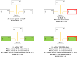
- 61850 Addition 2 adds Test Mode and Block Mode, which are very useful in testing.
-Test Mode: Relay Publishes GOOSE message with a Test Mode Flag = 1. Only Subscriber relays who are also are in Test Mode can read the message. If nothing else is in Test Mode, nothing will happen.
-Block Mode: Any contacts on the relay are prohibited from changing state. So, for “a” contacts, it’s like pulling the test switch and for “b” contacts it is like shorting the contact. Usually needed if this relay has any tripping / closing contacts
-These modes do not inherently affect things like sending a DTT or using proprietary protocols over serial cables. So, care needs to be taken to address these item. - GOOSE Message must follow the IEC61850 digital package design. This allows the messages to be interoperable i.e. a SEL relay can publish a message to a Siemens, GE & ABB relay and they should be able to understand it. These messages are set up as a data set that defines what you want to send. GOOSE Dataset have a max size limit.
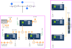
- CT & PT are wired into a relay. This relay then digitizes these analog quantities, which in turn is then Publishes out to Subscribing relays. This reduces CT /PT cables, CT burden and the likelihood of opening or grounding a CT.
- Publishing units fall into one of three categories:
-Basic Merging Units → Publish SV and wired to trip / close the CB via GOOSE
-Intelligent Merging Units → Does everything that Basic unit does, but will have additional features like BF, Reclosing or monitoring logicSAMU → Only publishes out - SV are typically sent over the Process Bus (PB) LAN. Sample rate is for the relays I have used is 4.8kHz or once sample every 0.208 mS ( about 80 samples a cycle). As a result, the PB has a lot of data on its network. So its best to limit other communication session on it.
- Requires a Precision Time Protocol ( PTP ) Clock signal. This is a highly accurate clock signal sent over the network. To make this happen, you need a clock capable of PTP and switches that have transparent clock capability to accurately transport PTP. Clocks are a critical aspect of SV and should not be taken lightly. Again, advance clock stuff out of scope.
- SV Message must follow the IEC61850 digital package design for interoperability.
- SV has Simulation Mode for testing. For example, if you have a 87B relay, you can simulate sending a current stream into the relay thru a test kit only connected to the network.
- Currently the digital package (i.e. data sets) for SV consist of 4 currents and 4 voltages. So, if you only want to send 3 currents (A, B & C phase), you still must leave the other spots blank. So, this take up bandwidth on the PB. This is changing and data sets are being created that allow you to put into up to 8 streams, your choice – 1 to 8 current, 1-8 voltages or any combo. Unused spots do not take up room in the digital package.
- Some venders offer a proprietary version of SV. These systems do not need a PB LAN and the clock signal is handled by the relay. So, it is simple, but it is not interoperable
MMS (Manufacturing Messaging Specifications)
- Is 61850 SCADA protocol, which is word based (as opposed to register / row based like DNP).
- Just like for GOOSE & SV, you create an MMS Data set for a relay.
-The sending / Publishing device (i.e. the relay) is referred to as the Server.
-The receiving / Subscribing device (i.e. the SCADA unit) is referred to as the Client
- MMS is sent out to the Client via reports. Reports are set up in the Server device
-Buffered → Data stored to some extent incase com is lost. You don’t want to make the storage too big, as it may affect the relays performance. Buffered reports are for things like CB status and other digital variables that could have momentary changes.
-Unbuffered → Com loss equals data loss. So things like analog values are good candidates for this. - There are alarms like LGOS that give you statistical info about GOOSE traffic and LSVS for SV. These are not available in DNP. It would be good to run these to the HMI for troubleshooting.
- MMS points that need Momentary Change Detect, should be mapped to the SER.
Network & LAN (Local Area Network)
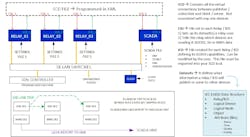
The signals for 61850 are sent on a LAN’s. These networks are made up of switches that can connect to devices via CAT 5 or fiber. Since the connection is to an IP port, other types of data are allowed besides GOOSE, SV & MMS. The other data includes: DNP3, Telnet, PTP, SNTP, Synchro phasors.
ARP & Ping commands are also available. ARP occurs when you first plug into a switch, letting it know what port it was connected to. “Hi Mom, I am home in my room”. A Ping checks to see if a relay is connected to a network. “John, are you home and can you hear me”
Now for 61850, things are typically broken down into two types of LAN’s.
- Station Bus (SB)
o Typically carries all communication types except SV
- Process Bus (PB)
o Used for SV
o Could run Goose on it also
The networks can be set up in a lot of different ways.
First there are different types of switches – RSTP vs SDN (Rapid Spanning Tree Protocol vs Software Defined Networks). The switch selection affects both how network reconfiguration takes place and how the flow of data is controlled.
RSTP switches are typically plug and play - data in a port goes out to all other ports. So messages like GOOSE and SV must be controlled using VLAN tagging. Network reconfiguration takes place using RSTP and doesn’t happen at protection speed.
SDN switches are not plug and play. They allow us to engineer both how the GOOSE and SV messages flow on the network and the alternate paths in the event of a network failure. This happens at protection speed.
Also, there are different failure designs: PRP & Fail Over.
Fail-Over uses a single LAN that reconfigures itself during a network fault and the device will switch from its primary to back up port based on link status detected by the relay. Things that should be evaluated.
PRP sends the same message out over two ports of the relay into separate LAN’s with a trailer appended to the message. PRP redundancy relies on the expectation that a network reconfiguration will not occur on each network at the same time. The devices simply use the first message that arrives and discards the duplicate.
My experience suggests that PRP is typically used by folks setting up a 61850 network. That being said, when things are not going as expected, the duplicate paths PRP networks use can make getting to root cause challenging. Carefully evaluate the pros and cons of your network design for cost, commissioning and maintenance of your 61850 system.
Next there are several connection methods: Ring, Meshed, Hub & Spoke. Your network design may dictate what type you use.
- Develop a good fiber plan. Redundant and easy to work on with equipment in service
- Reserve a Cat 5 engineering access port and make sure it can see all your devices and PTP
- If you are setting up a PB LAN for SV, make sure everything can handle PTP and have a good clock redundant design
Setting Up IEC61850
Relay and SCADA equipment will still have their normal settings file that governs how they operate. But when setting up an IEC61850 system, there is an additional information needed to control the flows between publisher / subscriber. These are the virtual wires. Additionally, the SCADA MMS Client / Server relationship needs to be established.
This happens in an SCD file. A chunk of it is sent to each relay via a CID file. Note if you are creating a multi-vender system, separate software will probably be required to build the SCD. This file is then imported by relay specific software to be sent to the relay.
Simple Example
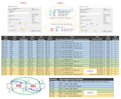
OK, so let’s set up a GOOSE Tripping scheme for the simple scheme shown in FIG 1. Note if multi-vender relays are being used, third party software is required to build the overall SCD file and then it gets imported into each manufacture’s software. This example is for a single vender relay system.
1. Define each Relay or IED
a. Select device that has the ICD file you want
b. Give the device an IP Address
2. Create a Data set for each relay based on what you want to send out. For this example it is:
BF Relay Send out CB Status and BF Trip
Line Relay sends out Line Trip
3. Create a GOOSE Transmit for each relay associated with its data set. This will require a unique Multicast MAC Address (you assign but needs to fit a format à First three Octets should be standard as shown for best practice. Also need to give it a VLAN Tag ID, App ID, Message name and GOOSE ID. These last two should be made as small as reasonably possible as they impact the message size. Note set GOOSE Tripping priority to 7 (highest). Also set the heartbeat time (max) and rapid repeat time (min). Min time if the data set value changes state and rapid repeats four times.
5. Program relays to receive Virtual Bit and respond accordingly. This includes mapping Message Quality Bits from each publish relay to an alarm variable in the subscribing relay for a GOOSE Trouble alarm. (Goes true if publisher heartbeat missing for 3 seconds per our example)
6. Load CID File to each relay
7. Program or otherwise enable TEST & BLOCK Mode in each relay
8. Verify GOOSE Message act as expected
9. Done. Go get a beverage of your choice
John Bettler, PE is the Principal Engineer for ComEd’s relay section. His team’s purview includes substation protection of distribution feeders up to 765kV transmission lines and all T&D equipment in between (TR / Buses / Cap / Inductors). The team also reviews interconnections, IPP and DER projects. As part of his duties, John is leading ComEd’s Digital Smart Substation (DSS) program, which utilizes IEC61850 Goose Messaging for its protection. His team has designed & installed seven substations and a lab. Currently they are installing their first brownfield 61850 site and have about 10 other substations in the design que. John developed a 61850 training class and has trained over 200 engineers and technicians on 61850 basics.
John is also adjunct faculty at Illinois Institute of Technology (IIT) and University of Wisconsin (UW) Madison teaching power & protection classes. He is a Licensed Professional Engineer (PE) in Illinois. He is working on his “Johnny P&C” brand for articles on fun things and training on all things power systems. John has a BSEE from Iowa State and a MSEE from Illinois Institute of Technology. John has worked at the Chicago area power company ComEd since 1990 and has experience as a field engineer and protection engineer.
About the Author
John Bettler
John Bettler, PE is the Principal Engineer for ComEd’s relay section. His team’s purview includes substation protection of distribution feeders up to 765kV transmission lines and all T&D equipment in between (TR / Buses / Cap / Inductors). The team also reviews interconnections, IPP and DER projects. As part of his duties, John is leading ComEd’s Digital Smart Substation (DSS) program, which utilizes IEC61850 Goose Messaging for its protection. His team has designed & installed seven substations and a lab. Currently they are installing their first brownfield 61850 site and have about 10 other substations in the design que. John developed a 61850 training class and has trained over 200 engineers and technicians on 61850 basics.
John is also adjunct faculty at Illinois Institute of Technology (IIT) and University of Wisconsin (UW) Madison teaching power & protection classes. He is a Licensed Professional Engineer (PE) in Illinois. He is working on his “Johnny P&C” brand for articles on fun things and training on all things power systems. John has a BSEE from Iowa State and a MSEE from Illinois Institute of Technology. John has worked at the Chicago area power company ComEd since 1990 and has experience as a field engineer and protection engineer.


